This thread has been locked.

If you have a related question, please click the "Ask a related question" button in the top right corner. The newly created question will be automatically linked to this question.

TMS320F28234: Tms320f28234

Part Number: TMS320F28234

Hi,

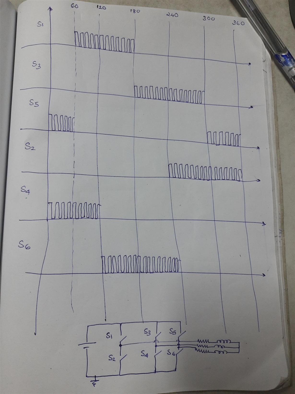
I want to generate pwm modulated gate pulses for 3phase inverter in 120degree conduction mode using f28234 DSP.I thought of providing the phase difference to each of 6 switches by using ePWM phase synchronization and modulating them by using the PWM chopper module.But pwm module can be synchronized with maximum of 3 pwm modules only.The second option available with me is to use GPIO for enabling the PWM fed switches  switching at the instant and use interrupt for obtaining the 120degree timing difference.Is there any other easier method to generate such a gate pulse?

  • Hi RESHMA,

    The easiest way seems to be generating 3 sine waves that 120 degree apart from each other.

    Best,

    John

  • Hi John,

    Thanks for your reply.I am new to DSP programming.Can you please elaborate what you are suggesting.I just want my 6 switches to be pulsed with 120degree mode of conduction.i.e during any particular instant one switch from the upper and one from lower arm conducts.

    Thanks,

    Reshma

  • Hi John,

    This is what I am trying to implement.

  • Reshma,

    You can synchronize all 6 PWM modules together if you wish. When doing this you will need to use ePWM 1 as the master and enable ePWM2 and ePWM4 to accept this signal into their sync chains. This information is described in the Datasheet( https://www.ti.com/lit/gpn/tms320f28234 ) because it is relevant when planning the layout of your board.

    For your convenience I have included a copy here.

    I *think* this will solve your issue. Please let me know if your issue is not resolved.

    Regards,
    Cody 

  • Hi Cody,

    First of all thank you for your reply.Till today I was not aware of ePWM4  be made slave to ePWM1. I forgot one point on my previous post.The square wave pulses are to be generated for 50Hz frequency and PWM pulses to be with 50kHz frequency.So if i proceed with your suggestion i require 50Hz to be generated by ePWM1 with 50kHz switching by using chopper module.But ePWM cant generate 50Hz signals.So this wont solve my issue.Waiting for your valid suggestion.

    Regards,

    Reshma

  • Reshma,

    I haven't checked, but i do not think you can chop the PWM signal at 1/1000th of the output frequency.

    It seems to make the most sense to me to make your PWMs output a 50 kHz signal and then use a separate timer or PWM to enable and disable the PWMs at a 50 Hz rate. You could then use something like the Trip zone, or set the duty cycle to 0%, or even enable and disable the continuous software force at the slower rate.

    It's not clear what you are trying to do, but if its a sinusoidal output using the PWM then you will need to vary your duty cycle at a function of your carrier frequency in relation your desired sine output frequency.

    Regards,
    Cody 
     

  • Hi Cody,

    Thanks for your reply.I was trying to proceed in this way only.I inquired to  know if some alternative using PWM module is available or not.Actually I was trying to implement blind startup logic for BLDC motors.Instead of motor,I will be using an RL load for time being.Hope it works fine.

    Thanks and Regards,

    Reshma

  • Reshma,

    good to hear! Feel free to start another thread if you have other questions.

    Regards,
    Cody