


Dear team:
I had a problem with the routine of "HVBLDC_Sensored" in "HVMotorCtrl+PfcKit_v2.1".
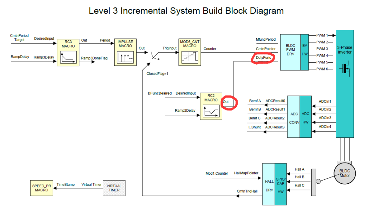
In Level 3 of the routine, it can be seen from the schematic diagram that the duty cycle input of PWM is "rmp2.out", as shown in the following figure:
But in the level 3 program:
if (ClosedFlag==TRUE)  {
     if (hall1.CmtnTrigHall==0x7FFF) {

      PreviousState = pwm1.CmtnPointer;


// Comment the following if-else-if statements in case of
// inverted Hall logics for commutation states.
      if (hall1.HallGpioAccepted==5)
        pwm1.CmtnPointer = 0;

      else if (hall1.HallGpioAccepted==1)
        pwm1.CmtnPointer = 1;

      else if (hall1.HallGpioAccepted==3)
        pwm1.CmtnPointer = 2;

      else if (hall1.HallGpioAccepted==2)
        pwm1.CmtnPointer = 3;

      else if (hall1.HallGpioAccepted==6)
        pwm1.CmtnPointer = 4;

      else if (hall1.HallGpioAccepted==4)
        pwm1.CmtnPointer = 5;


/*

// Comment the following if-else-if statements in case of
// non-inverted Hall logics for commutation states.
      if (hall1.HallGpioAccepted==2)
        pwm1.CmtnPointer = 0;

      else if (hall1.HallGpioAccepted==6)
        pwm1.CmtnPointer = 1;

      else if (hall1.HallGpioAccepted==4)
        pwm1.CmtnPointer = 2;

      else if (hall1.HallGpioAccepted==5)
        pwm1.CmtnPointer = 3;

      else if (hall1.HallGpioAccepted==1)
        pwm1.CmtnPointer = 4;

      else if (hall1.HallGpioAccepted==3)
        pwm1.CmtnPointer = 5;

*/
    }    //hall1.CmtnTrigHall == 0x7FFF
  } // ClosedFlag==TRUE
  else

      pwm1.CmtnPointer = (int16)mod1.Counter;
      pwm1.DutyFunc = DfuncTesting;
      BLDCPWM_MACRO(1,2,3,pwm1)
“pwm1.DutyFunc = DfuncTesting;” This shows that the duty cycle input of PWM is still the parameter of open-loop, and "rmp2.out" is not taken as the duty cycle input.
Did I get it wrong?
Best Regards
