This thread has been locked.
If you have a related question, please click the "Ask a related question" button in the top right corner. The newly created question will be automatically linked to this question.
Tool/software: Code Composer Studio
Hi,
I am working on internal ADC and using 3.3V Internal reference. I am unable to get closer ADC value.
Now I set sample window duration (ACQPS+1) as 6. I want to verify whether my ACQPS set is correct.
I am using 80 MHz SYSCLCK and ADCCLK = 20 MHz (SYSCLCK/4).
The duration of the S+H window is controlled by (ACQPS + 1) SYSCLK cycles.
To determine ACQPS, I got solution from forum: https://e2e.ti.com/support/microcontrollers/c2000/f/171/t/708950?TMS320F28377S-Calculate-the-right-ACQPS-value-of-C2000-s-ADC
From my datasheet I found :
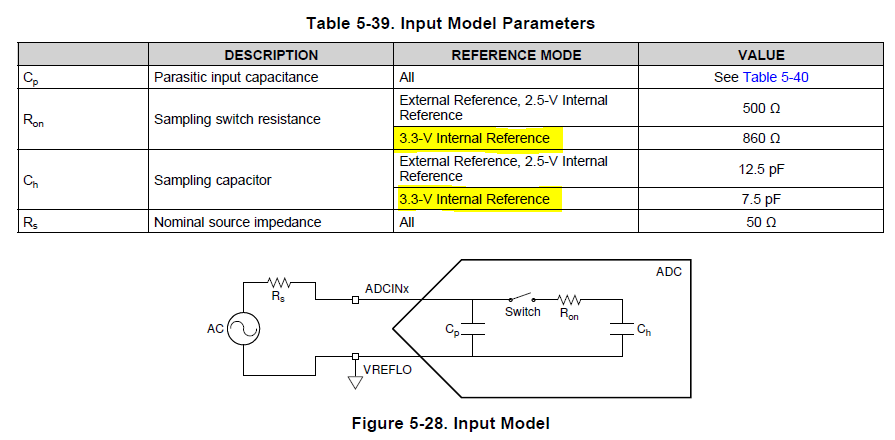
I want to set accuracy to 0.5 LSB the time constant should be –ln(0.5/2^12)=9.01
T(S+H) = 9.01 *( (860 Ω *+ 50 Ω)*(7.5 pF)) = 61.5 ns.
(ACQPS +1) = T(S+H) * SYSCLK
= 61.5 ns * 80 MHz = ~5
So ACQPS is 4.
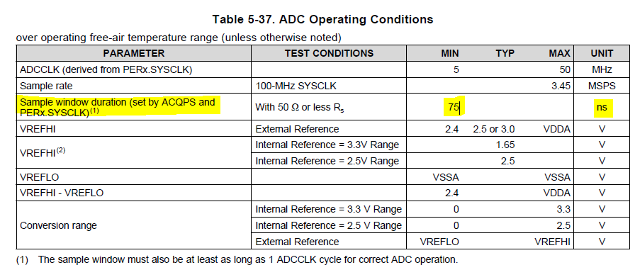
From above table, min sample window duration is 75ns.
(ACQPS +1) = T(S+H)min * SYSCLK
= 75 ns * 80 MHz = 6
Here ACQPS is 5.
Which calculation is correct to select ACQPS? or ACQPS can be selected more that 5.
Also I found that the sample window must also be at least as long as 1 ADCCLK cycle for correct ADC operation. How to verify it?
Regards
Monish P
Hi Monish,
In the equations above, you have assumed 50 ohm source impedance (Rs) and 0pF of source capacitance (Cs), but what is actually driving the ADC? These two values will be specific to your ADC driver/source.
These equations also assume that there isn't any inductance from cabling or jumper wires (everything is on a PCB) and that the driving op-amp is not the limiting factor (should be true if the op-amp has BW in the 10's of MHz)
For a more in-depth treatment than the TRM section, have a look at the "SAR ADC Input Driver Design" series from TI precision labs : https://training.ti.com/node/1139106?context=1139747-1140267-1128375-1139106
From this, note that the optimum source capacitance would be around 20x Ch (so ~150pF).
A simple experiment to tell if the settling is adequate is to repeatedly sample a DC input voltage near mid-scale in the sequence 3.3V --> Channel Under Test --> 0V --> Channel Under test. If there is an average difference between the first and second sample, this could indicate inadequate S+H time. Note that on this device there is a quirk where you'd want to use all even number channels or all odd numbered channels to do this test (e.g. CH14 -> CH0 -> CH2 -> CH0)
Also note that it would not be recommended to run the ADCCLK at 20MHz in this case; there is no power savings or other known advantage to running a slower ADCCLK. You should try to get as close to the max ADCCLK (50MHz) as the dividers allow (so use 80MHz / 2 = 40MHz)