Other Parts Discussed in Thread: LAUNCHXL-F28027, UNIFLASH, TMS320F28027, BOOSTXL-DRV8301, MOTORWARE,
Hi,
Here's what I've tried:
- All of the FAQ connection items as below within the LAUNCHXL-F28027 C2000 Piccolo LaunchPad Experimenter Kit User's Guide SPRUHH2C Revised March 2019.
With reference to the FAQ about ensuing jumpers present on JP1, JP2 and JP3, the LaunchXL PCB infact lacked a JP2 header, I had to solder one on to try this!
About ensuring drivers are correctly installed, by ensure do TI mean google around until something is found, because that's what I had to do. I chanced upon UniFlash,
installation of which gained me within DevMgr, a Texas Instruments Debug Probes section, containing XDS100 Class Auxiliary Port and XDS100 Class Debug Port,
when the LaunchXL is connected. No TI XDS100 Channel A/B entries within the USB Serial Controller section. This driver addition, and having JP2 jumper fitted,
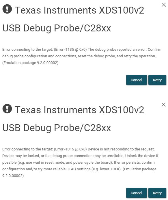
and JP1 and/or JP2 jumper fitted, elevates error 1135 to 1015. And lights as well as the a red LED near the USB connection, a green LED near board centre,
and four blue LEDs at board opposite end. The red and green LEDs I presume are the two power LEDs that the FAQ cites.
- Trying to connect with UniFlash, same two errors in same circumstances. Error wording as attached
- Trying CCS Test Connection, per TMS320F28027_xds100v2.ccxml > Basic > General Setup > Experimenter's Kit - Piccolo F28027 > Test Connection. Just reports no hardware, per transcript below.
- A different USB-A to Mini-USB cable
- Rebooting PC
- Using LaunchXL reset button
- Connecting BOOSTXL-DRV8301 board and supplying 12VDC power to its supply terminals
The problem encountered while following the worked Motorware examples, at the point of trying to the download first sample, Lab1
Best regards,
David
FAQ items
=========
3. Why can’t I connect to the LaunchPad in Code Composer Studio?
There are a number of things that could cause this and they all have an easy fix.
• Is S1 switch 3 in the down position?
This is the TRST pin that enables and disables JTAG functionality on the chip. This switch must be
in the up position for the debug probe to be able to connect.
• Are both power LEDs lit?
The board has two power domains because of the isolated JTAG interface. For low-voltage
application development, JTAG isolation is not needed and the power domains can be combined to
allow for convenience (that is, the board can be powered completely through the USB). Ensure that
jumpers are placed on the posts of JP1, JP2, and JP3.
• Are drivers correctly installed for the XDS100v2 present on the LaunchPad?
Right click on My Computer and select properties. Navigate to the Hardware tab in the dialog box
and open the device manager. Scroll to the bottom of the list and expand the USB Serial Bus
controllers item. Are there two entries for TI XDS100 Channel A/B? If not, try unplugging and
replugging in the board. Does Windows give you any messages in the system tray? In Device
Manger, do either of the entries have a yellow exclamation mark over their icon? If so, try
reinstalling the drivers.
Test Connection results
=======================
[Start: Texas Instruments XDS100v2 USB Debug Probe_0]
Execute the command:
%ccs_base%/common/uscif/dbgjtag -f %boarddatafile% -rv -o -F inform,logfile=yes -S pathlength -S integrity
[Result]
-----[Print the board config pathname(s)]------------------------------------
C:\Users\david\AppData\Local\TEXASI~1\CCS\
ccs1020\0\0\BrdDat\testBoard.dat
-----[Print the reset-command software log-file]-----------------------------
This utility has selected a 100- or 510-class product.
This utility will load the adapter 'jioserdesusb.dll'.
The library build date was 'Jan 1 2021'.
The library build time was '11:25:57'.
The library package version is '9.3.0.00032'.
The library component version is '35.35.0.0'.
The controller does not use a programmable FPGA.
The controller has a version number of '4' (0x00000004).
The controller has an insertion length of '0' (0x00000000).
This utility will attempt to reset the controller.
This utility has successfully reset the controller.
-----[Print the reset-command hardware log-file]-----------------------------
The scan-path will be reset by toggling the JTAG TRST signal.
The controller is the FTDI FT2232 with USB interface.
The link from controller to target is direct (without cable).
The software is configured for FTDI FT2232 features.
The controller cannot monitor the value on the EMU[0] pin.
The controller cannot monitor the value on the EMU[1] pin.
The controller cannot control the timing on output pins.
The controller cannot control the timing on input pins.
The scan-path link-delay has been set to exactly '0' (0x0000).
-----[The log-file for the JTAG TCLK output generated from the PLL]----------
There is no hardware for programming the JTAG TCLK frequency.
-----[Measure the source and frequency of the final JTAG TCLKR input]--------
There is no hardware for measuring the JTAG TCLK frequency.
-----[Perform the standard path-length test on the JTAG IR and DR]-----------
This path-length test uses blocks of 64 32-bit words.
The test for the JTAG IR instruction path-length failed.
The JTAG IR instruction scan-path is stuck-at-ones.
The test for the JTAG DR bypass path-length failed.
The JTAG DR bypass scan-path is stuck-at-ones.
-----[Perform the Integrity scan-test on the JTAG IR]------------------------
This test will use blocks of 64 32-bit words.
This test will be applied just once.
Do a test using 0xFFFFFFFF.
Scan tests: 1, skipped: 0, failed: 0
Do a test using 0x00000000.
Test 2 Word 0: scanned out 0x00000000 and scanned in 0xFFFFFFFF.
Test 2 Word 1: scanned out 0x00000000 and scanned in 0xFFFFFFFF.
Test 2 Word 2: scanned out 0x00000000 and scanned in 0xFFFFFFFF.
Test 2 Word 3: scanned out 0x00000000 and scanned in 0xFFFFFFFF.
Test 2 Word 4: scanned out 0x00000000 and scanned in 0xFFFFFFFF.
Test 2 Word 5: scanned out 0x00000000 and scanned in 0xFFFFFFFF.
Test 2 Word 6: scanned out 0x00000000 and scanned in 0xFFFFFFFF.
Test 2 Word 7: scanned out 0x00000000 and scanned in 0xFFFFFFFF.
The details of the first 8 errors have been provided.
The utility will now report only the count of failed tests.
Scan tests: 2, skipped: 0, failed: 1
Do a test using 0xFE03E0E2.
Scan tests: 3, skipped: 0, failed: 2
Do a test using 0x01FC1F1D.
Scan tests: 4, skipped: 0, failed: 3
Do a test using 0x5533CCAA.
Scan tests: 5, skipped: 0, failed: 4
Do a test using 0xAACC3355.
Scan tests: 6, skipped: 0, failed: 5
Some of the values were corrupted - 83.3 percent.
The JTAG IR Integrity scan-test has failed.
-----[Perform the Integrity scan-test on the JTAG DR]------------------------
This test will use blocks of 64 32-bit words.
This test will be applied just once.
Do a test using 0xFFFFFFFF.
Scan tests: 1, skipped: 0, failed: 0
Do a test using 0x00000000.
Test 2 Word 0: scanned out 0x00000000 and scanned in 0xFFFFFFFF.
Test 2 Word 1: scanned out 0x00000000 and scanned in 0xFFFFFFFF.
Test 2 Word 2: scanned out 0x00000000 and scanned in 0xFFFFFFFF.
Test 2 Word 3: scanned out 0x00000000 and scanned in 0xFFFFFFFF.
Test 2 Word 4: scanned out 0x00000000 and scanned in 0xFFFFFFFF.
Test 2 Word 5: scanned out 0x00000000 and scanned in 0xFFFFFFFF.
Test 2 Word 6: scanned out 0x00000000 and scanned in 0xFFFFFFFF.
Test 2 Word 7: scanned out 0x00000000 and scanned in 0xFFFFFFFF.
The details of the first 8 errors have been provided.
The utility will now report only the count of failed tests.
Scan tests: 2, skipped: 0, failed: 1
Do a test using 0xFE03E0E2.
Scan tests: 3, skipped: 0, failed: 2
Do a test using 0x01FC1F1D.
Scan tests: 4, skipped: 0, failed: 3
Do a test using 0x5533CCAA.
Scan tests: 5, skipped: 0, failed: 4
Do a test using 0xAACC3355.
Scan tests: 6, skipped: 0, failed: 5
Some of the values were corrupted - 83.3 percent.
The JTAG DR Integrity scan-test has failed.
[End: Texas Instruments XDS100v2 USB Debug Probe_0]