


Part Number: C2000WARE-MOTORCONTROL-SDK
Other Parts Discussed in Thread: DRV8320, INA240, LAUNCHXL-F280049C, BOOSTXL-DRV8320RS, MOTORWARE, LAUNCHXL-F28379D, BOOSTXL-3PHGANINV
Hello!
I've been developing sensorless motor controler using InstaSPIN-FOC and FAST observer for couple months now.
I did similar design before using non-TI MCU, but I had so many problems with full-load startup and tuning motor + observer + foc parameters that i decided to try InstaSPIN, despite the fact i was scared of the different MCU architecture, etc.
I've faced many problems during the design, while one of them is major and project mucking.
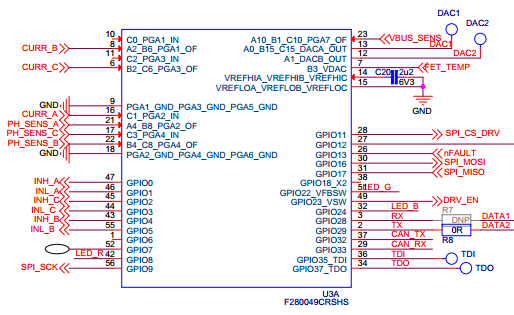
Custom PCB:
F280049C, DRV8320 + Infineon metal FETs
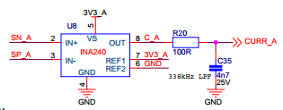
Triple 1mΩ in-line shunts with INA240 CSAs.
Plenty of bulk+decoupling capacitor on the board.
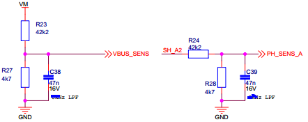
Vph +Vm sensing #1: 4.7k, 42.2k, 47nF Vph sens: 33V max, 800.7Hz.
Vph +Vm sensing #2: 82nF -> 459Hz.
Iph sensing: +/-82.5A range.
Motor parameters:
800W, 12n14p SM-PMSM / hobby BLDC, "quasi"-sinusoidal BEMF, sinusoidal current,
~22-25mΩ, 25-30µH, 300kV (~2.9mWb)
Load:
Speed-varying exponentially / Air/Fan Propeller
No load: 0.8A DC 6000RPM (700Hz)
Static: 1.4 Nm, 800W, 40A DC @ 4500RPM (525Hz),
With airflow: ~400-500W @5000RPM (580Hz; space for overmodulation/field-weakening)
Dynamic on steps: 1.5 Nm, 1100W, 60A DC.
(Values above tested with 6-step BLDC controller and 5-cell battery)
Battery:
5-cell Lithium 18.5V, 21.0V max
Software:
It's based on is05_motor_id lab example for motor identification procedure and is13_fw_mtpa lab example for the main working code.
PWM/ISR frequency set to 20/20 kHz. Current loop bandwidth is set to 1kHz. Max Vs modulation is < 0.57. FWC set off.
Also, I didn't modify ADC triggering for better in-line shunt utilization and it runs default, same as with low-side.
My problems/questions:
1. Starting from LAUNCHXL-F280049C + BOOSTXL-DRV8320RS I wasn't able to run motor at speed higher than ~330-350Hz, which was close to Vph filters cutoff frequency. I changed the circuit and set those filters to about ~1000Hz and the problem was solved (sort of). Using that knowledge, the custom PCB was designed with Vph sensing #1 (800Hz).
InstaSPIN-FOC User's Guide recommends to set the cutoff in 300-400Hz range, even if the motor is spinning much quicker and there are some reference guides with similar approach with drone motor running at 1600Hz. There are also numerous repeating forum threads (especially with 28004x chips) with the same problem I had.
As papers are quite outdated and misleading, can someone "with access" explain what's hidden behind it and how this filter affect the estimator?
2. Even with filters set to 800Hz, the controller was still loosing stability under load at around 480-500Hz, causing huge current spikes. Without load I was able to spin the motor up to 600-700Hz depending on overmodulation and field-weakening settings. I've done multiple tests trying to find the problem and eliminated:
- PID loops: The same problem was occuring at closed speed loop, closed torque loop, open loop controlling Vq and closed Id=0, dual open loop controlling Vq and Vd=0.
- DC bus utilization: Problem was occuring around the same speed when testing at 5 or 6-cell battery at different current levels.
- Overmodulation was set to off
- Field-weakening was off
- Tested at multiple PWM switching frequencies
- Same limit applied to LAUNCHXL-F280049C + BOOSTXL-DRV8320RS, but I thought It was related to dc bus utilization limit and hoped that in-lines could solve the problem.
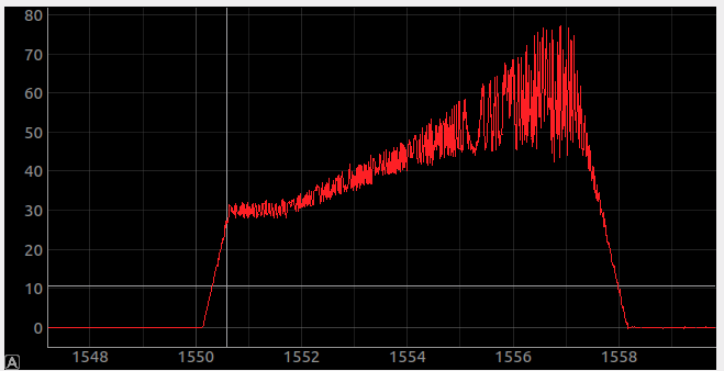
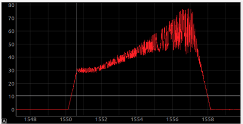
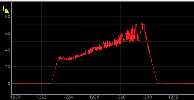
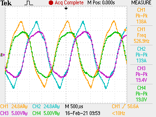
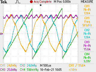
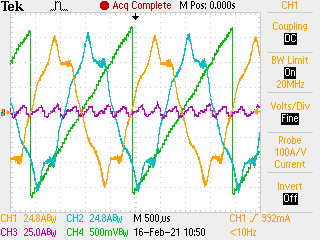
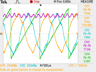
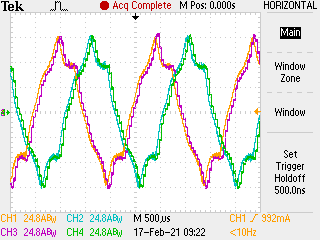
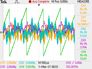
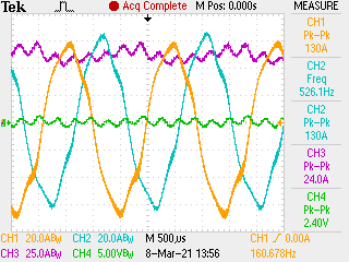
This is 60A Iq datalog graph from eval board with huge current spikes:
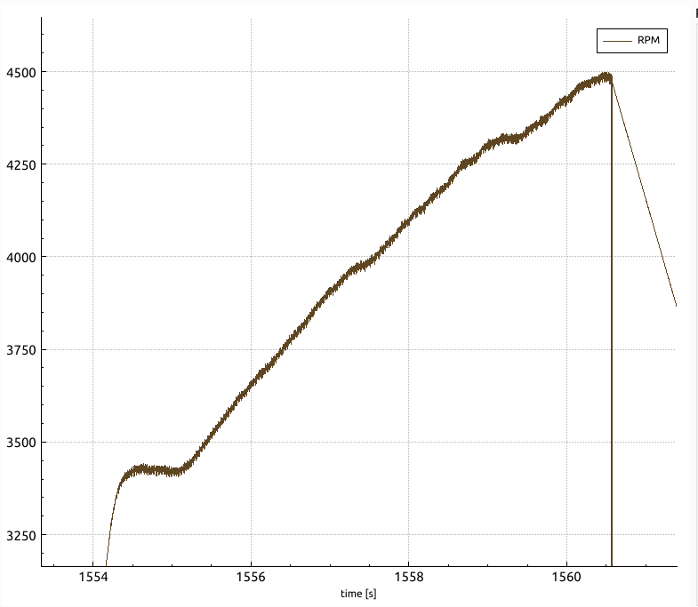
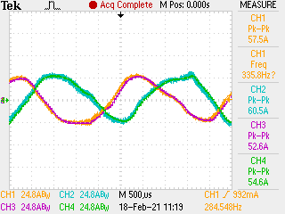
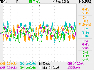
And these are graphs from the dyno using custom pcb. I have limited debugging options so I can't provide more detailed signals until i receive current probes and set up the equipment safely for tests under the load.
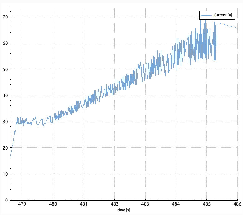
Current is measured on battery leads.
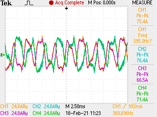
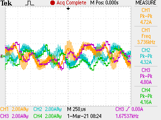
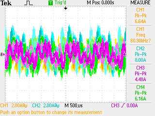
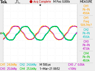
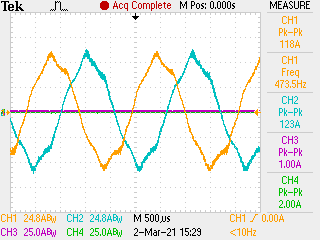
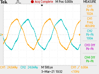
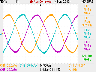
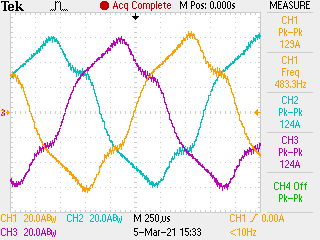
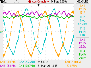
Full load startup at 5S: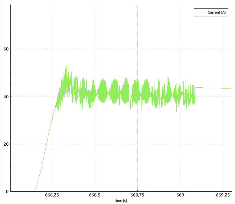
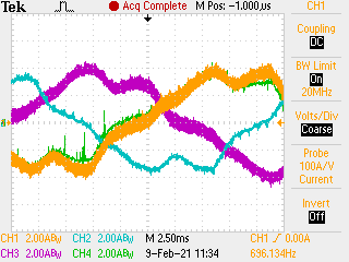
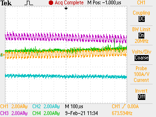
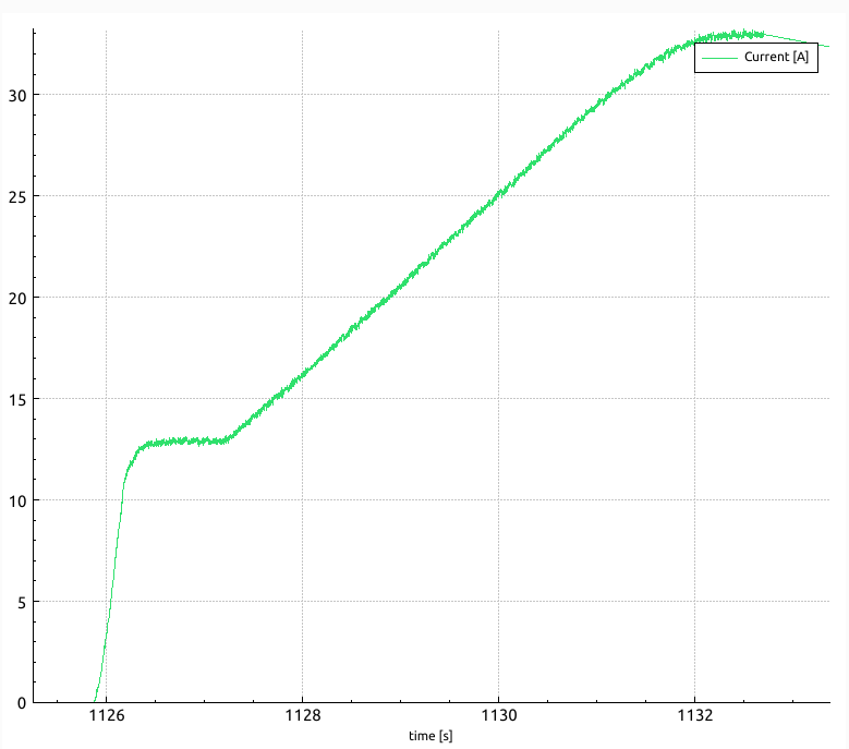
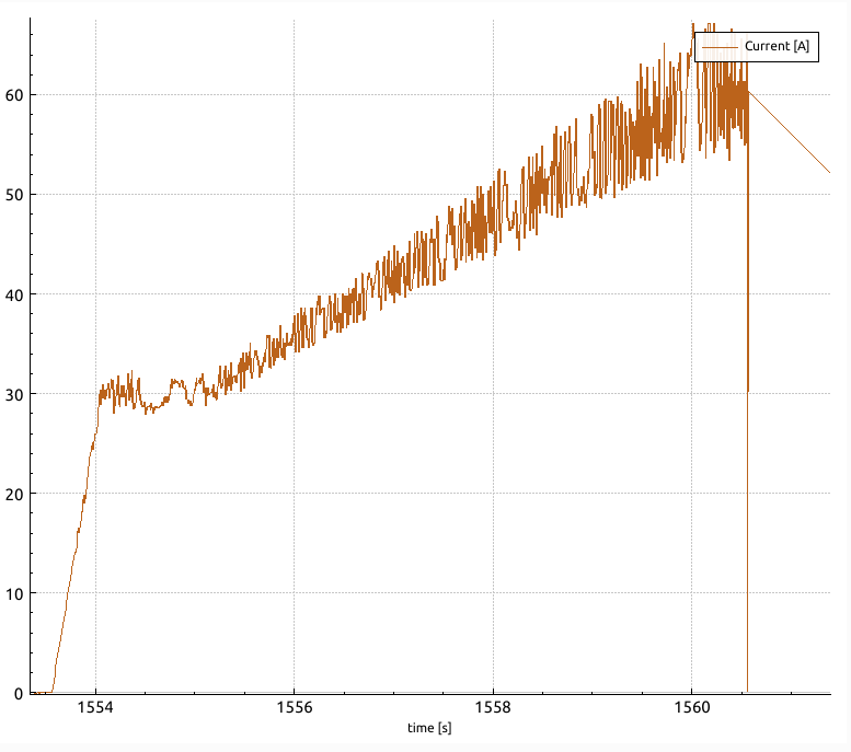
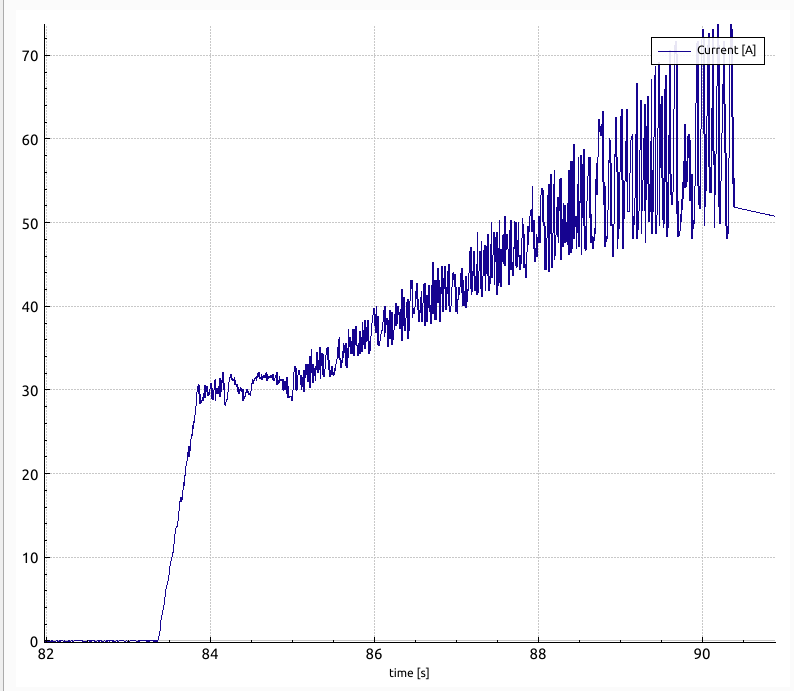
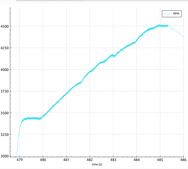
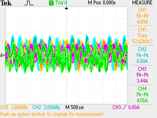
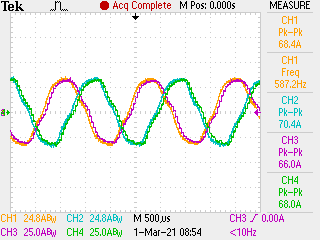
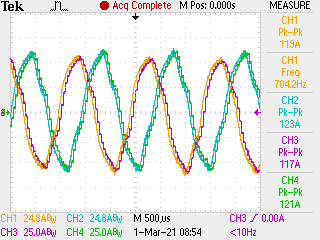
Sweep at 5S + current chart: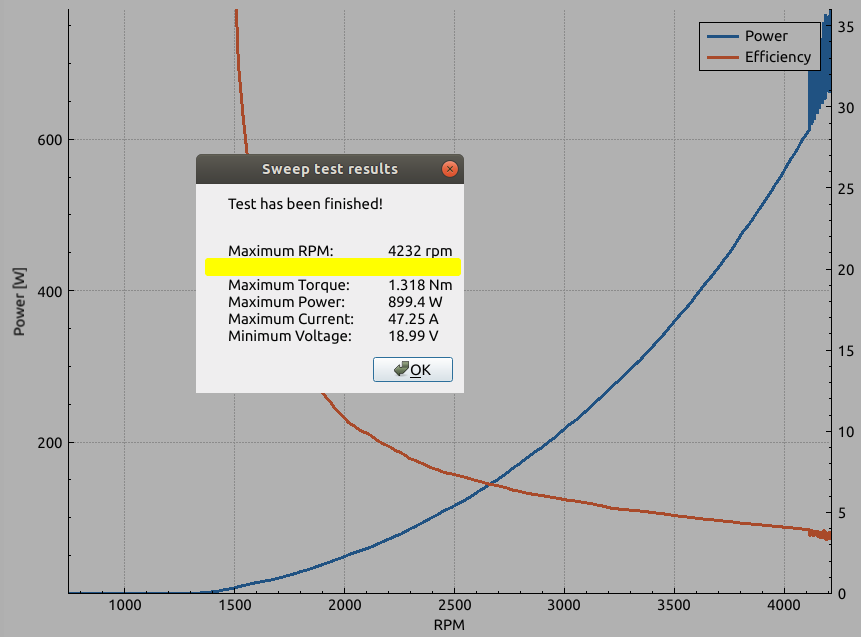

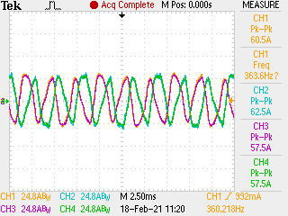
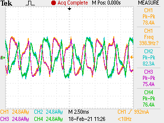
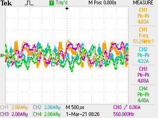
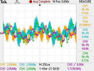
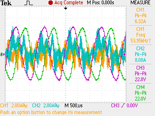
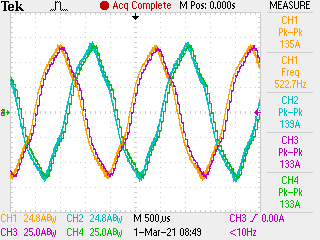
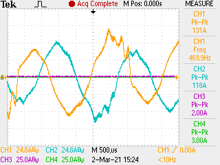
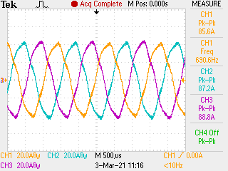
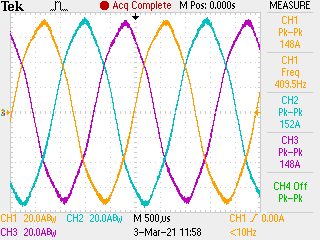
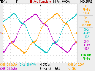
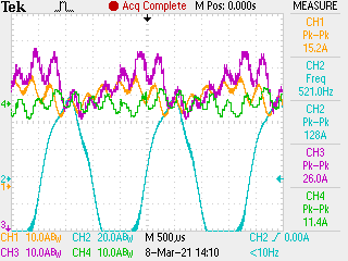
Full load startup at 6S: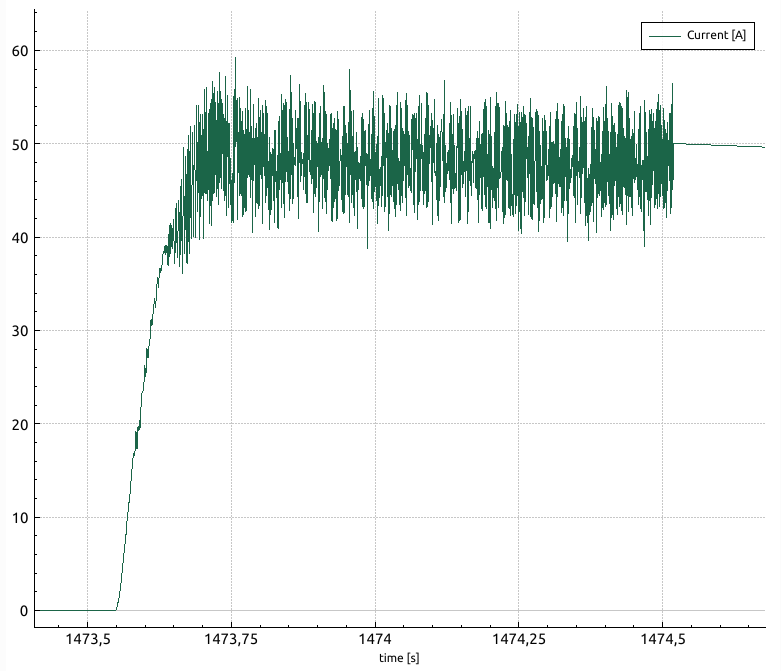
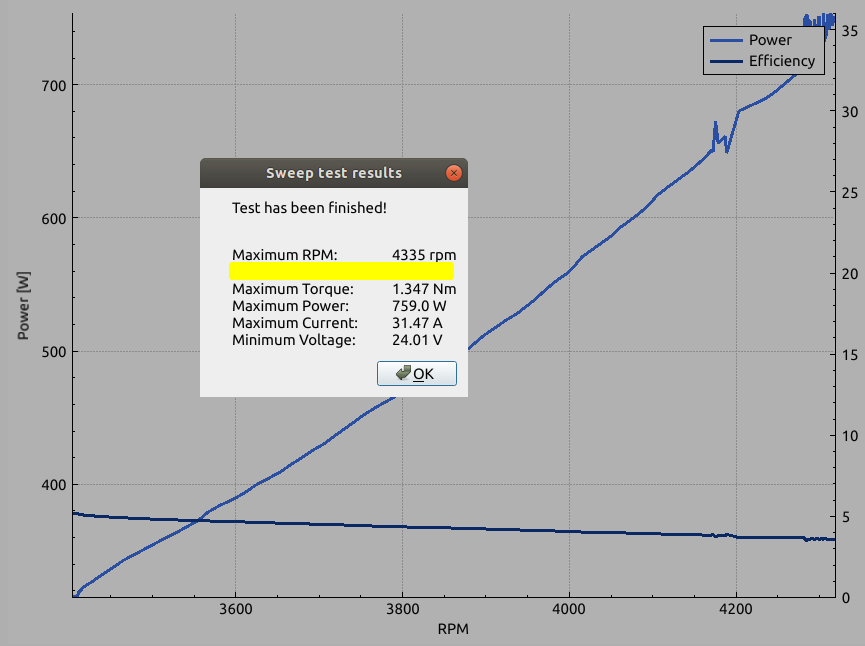
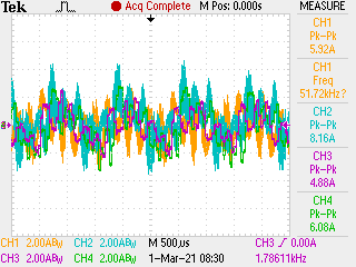
Sweep at 6S + current chart:

3. SDK 3.01.00.00 update provided additional access to hidden estimator parameters through fluxHF.lib functions: EST_setOneOverFluxGain_sf(), EST_setFreqLFP_sf(), EST_setBemf_sf().
There is no documentation about these parameters, what exactly do these change and no information how to tune or test them. I found some threads on this forum which helped me to tune them a little and they seemed to partially fix problem nr. 1. - so I was able to use Vph sensing #2 (459Hz) circuit and partially fix problem nr. 2.
Even after the fluxHF fix, the controller still works far from the optimal point.
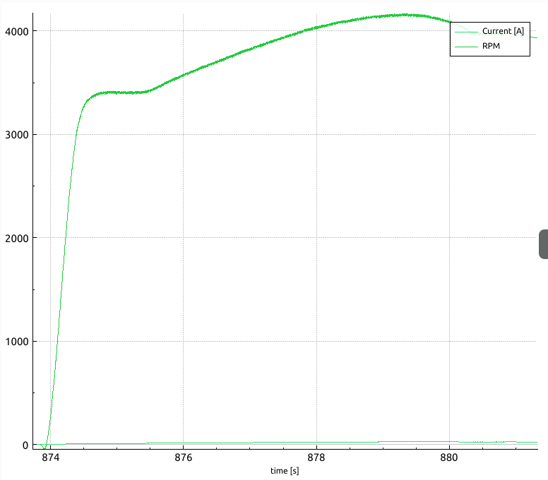
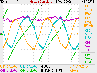
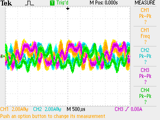
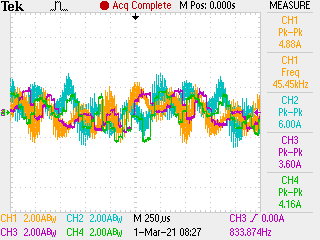
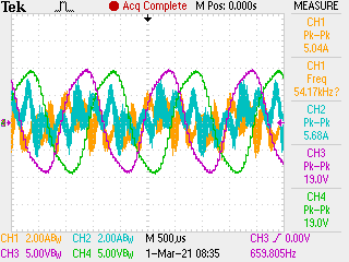
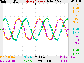
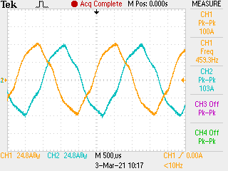
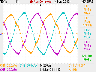
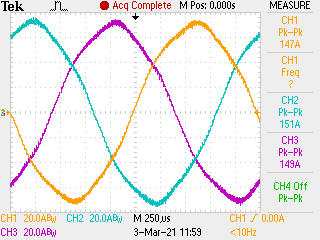
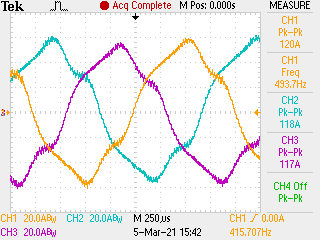
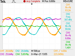
Full load startup at 5S: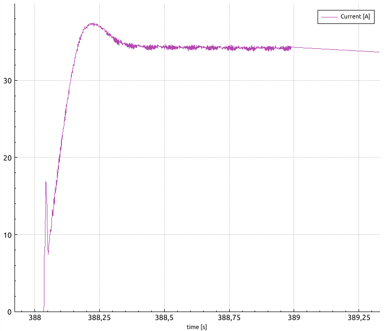
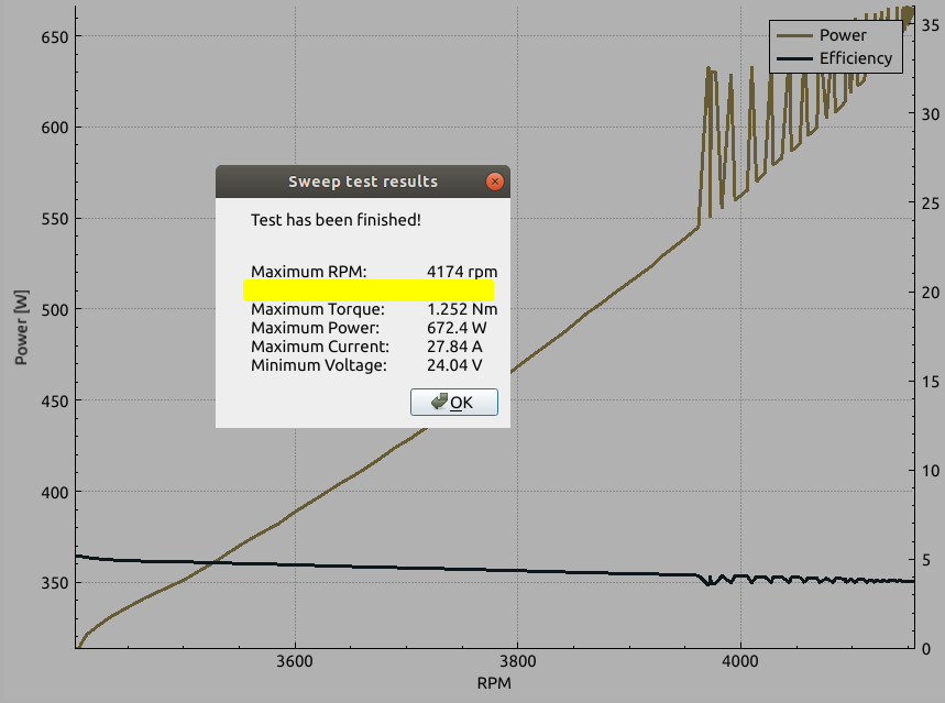
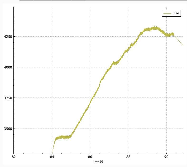
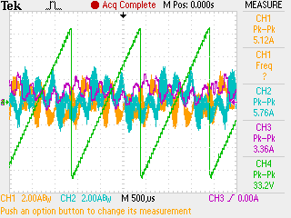
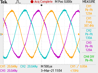
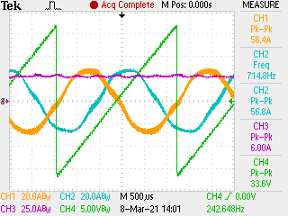
And sweep at 6S still showing some twitch around ~4000RPM and performance/efficiency drop after that: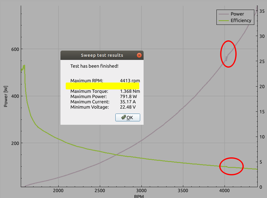
Also after i tuned those 3 parameters, i tried different motor, performed motor identification procedure and wasn't able to achieve the same performance as with previous motor, unless i tuned the 3 parameters again! Second motor was spinning up to 3700 rpm. It's unacceptable for me to tune those parameters for each motor separately.
A. How are those parameters connected to nr. 1 problem? Is it more optimal to stay on #1 Vph sensing, which works doesn't require fluxHF parameters or #2, closer to values that user guide suggests.
B. How can i debug and tune those parameters perfectly to not loose performance?
C. Are there still some parameters that can be tuned inside the estimator that could fix those issues?
Until SDK 3.01.00.00 release I thought the problem was related to my HW and SW modifications, but this clearly shows that stability problem is mainly related to the built-in FAST estimator and i've lost the hope that i'm able to fix it on my own.
4. Are InstaSPIN ROM estimators tuned differently between TI's MCUs? If switched to different MCU, maybe with "-MOTION" one, could the estimator work better with my motor? If yes, what are the options?
5. How can i optimize the code for in-line current sensing? Can it provide any benefits over low-side ones? Seems that INA240 amplifiers are quite slower than low-side shunts and built-in PGAs. I want to utilize as much battery as i can, because i'm switching from 6-step drive to FOC, while can't change the battery and must keep the performance level. That's why I went for the in-lines, but I think I'd need to modify the ADC triggering to really use them.
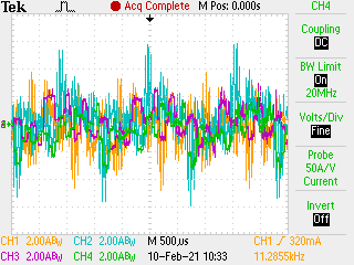
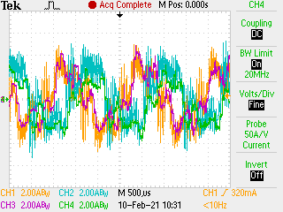
6. How to tune IDRIVE settings? I did some tests without motor connected and
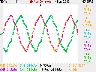
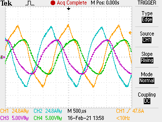
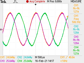
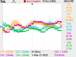
Observed distortion graphs with the default settings, Isource=1A, Isink=2A:
CH1: VGL, CH2: VDSL, CH3: VGH, CH4:VDSH
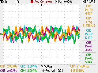
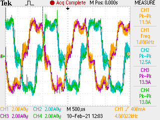
High-side rise: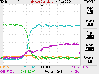
Low-side rise:
So I've tuned it down to Isource=0.44A for Tr=100ns on HS, Isource=0.33A for Tr=133ns on LS and left Isink=2A for Tf=22ns for both, which eliminated the distortions without the motor.
It is the right way? With the motor, those graphs looks smooth even at default settings.
Also, how to properly set switching deadtime? I set it to 200ns for safety, but with smart gate driver "handshakes" could i set it to 50 or 100ns and still be safe while keeping max performance?
6. Is +/- 82.5A current sense range enough for this motor? I'm close to maxing it out with about Iq =~60A, but when i tried doubling it up with 0.5mΩ shunts to avoid saturation, the controller wouldn't run due to extra noise and lack of precision.
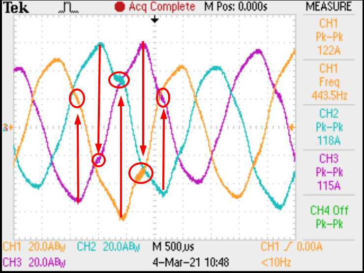
7. Did anyone observe that B phase currents are less noisy than the other two? I've tested it on both custom hardware and eval board, also changing probes, motor wires... with same observations. Is there some current injection causing that?
8. Is 20kHz optimal for the motor? I'd want to run it at higher frequency, but then inverter requires quite more switching current and there is less sampling time for current measurements. Also on higher PWM frequency, the motor becomes audibly noisier (shouldn't be the opposite?), especially on current offset calibration (50% modulation) and there are more disturbances on Iq current when the motor is on standstill. What could have caused that? The tests were done keeping the ISR frequency: PWM20/ISR20, 40/20 and 60/20 kHz.
Sum up:
That's quite a few complicated questions, but i hope to receive as many answers as possible and get this project going. I plan to provide more tests with proper signal graphs when I'll receive current probes. Those would also help identifying potential HW sensing problems etc.
I really like TI's built-in motor identification, easy tuning (despite fluxHF) and I'm very impressed with 0/low speed performance. But It's all for nothing if I can't achieve required full-power performance. Until the SDK update, I was close to giving up. After that, i think It's quite close to solve it and push the performance even further with OVM and FW algorithms.
Regards,
Mateusz


