This thread has been locked.

If you have a related question, please click the "Ask a related question" button in the top right corner. The newly created question will be automatically linked to this question.

MOTORWARE: motorware

Part Number: MOTORWARE
Other Parts Discussed in Thread: TMS320F28379D

Hi TI

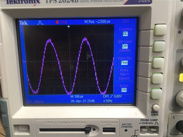
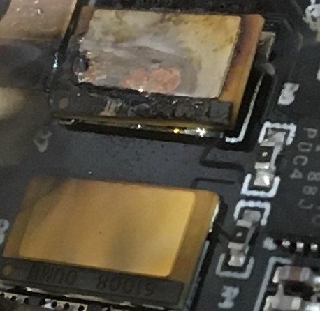
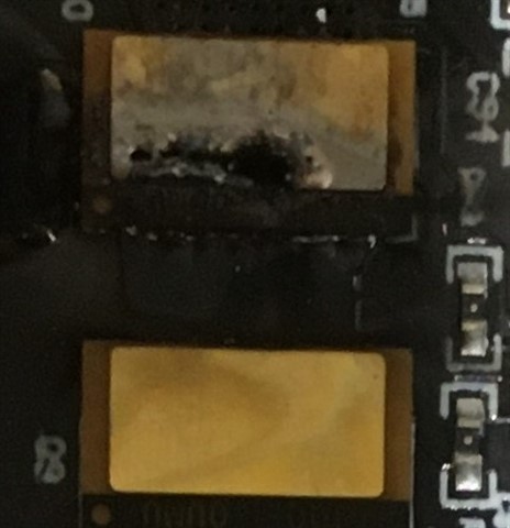
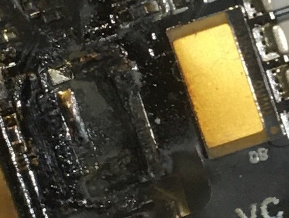
For our high speed, ultra-low inductance motor the switches burst instantly in the first pulses.

we ran a motor with inductance of 300 uH successfully but for the following one the power switches explode everytime. 

The inductance is 47 uH.

 #define USER_IQ_FULL_SCALE_FREQ_Hz (1400.0)
#define USER_ADC_FULL_SCALE_VOLTAGE_V (120)
#define USER_IQ_FULL_SCALE_CURRENT_A (250.0)
#define USER_ADC_FULL_SCALE_CURRENT_A (250.0)

#define USER_PWM_FREQ_kHz (100.0)
#define USER_MAX_VS_MAG_PU (0.6666)
#define USER_NUM_PWM_TICKS_PER_ISR_TICK (3)

#define USER_NUM_ISR_TICKS_PER_CTRL_TICK (1)

#define USER_NUM_CTRL_TICKS_PER_CURRENT_TICK (1)
#define USER_NUM_CTRL_TICKS_PER_EST_TICK (1)
#define USER_NUM_CTRL_TICKS_PER_SPEED_TICK (90)
#define USER_NUM_CTRL_TICKS_PER_TRAJ_TICK (90)

#define USER_R_OVER_L_EST_FREQ_Hz (300)
define USER_ZEROSPEEDLIMIT (2 / USER_IQ_FULL_SCALE_FREQ_Hz)
#define USER_VOLTAGE_FILTER_POLE_Hz (1200.0)

#define USER_MOTOR_TYPE MOTOR_Type_Pm
#define USER_MOTOR_NUM_POLE_PAIRS (1)
#define USER_MOTOR_Rr (NULL)
#define USER_MOTOR_Rs (0.02)
#define USER_MOTOR_Ls_d (0.000047)
#define USER_MOTOR_Ls_q (0.000047)
#define USER_MOTOR_RATED_FLUX (0.0148)
#define USER_MOTOR_MAGNETIZING_CURRENT (NULL)
#define USER_MOTOR_RES_EST_CURRENT (1.0)
#define USER_MOTOR_IND_EST_CURRENT (-0.5)
#define USER_MOTOR_MAX_CURRENT (100)
#define USER_MOTOR_FLUX_EST_FREQ_Hz (20.0)


Does anyone have a similar experience? What could be done to prevent this and run the motor.

Many thanks 

  • Which controller are you using?

    It seems like the control frequency (100/3) is too high for instaspin-foc in motorWare. We recommend the control frequency is lower than 20kHz for F2802xF/05xF, and 25kHz for F2806xF.

    Do you run the motor with speed-close loop? If yes, the  USER_NUM_CTRL_TICKS_PER_SPEED_TICK is too large for speed control.

    Did you implement the overmodulation and current re-construction as lab10a since USER_MAX_VS_MAG_PU is equal to 0.666? You might set the USER_MAX_VS_MAG_PU as lower than 0.57, and see what happens. It requires very high-quality current sensing signals on the hardware board if USER_MAX_VS_MAG_PU is higher than 0.57.

  • Which controller are you using?

    F28069M

    It seems like the control frequency (100/3) is too high for instaspin-foc in motorWare. We recommend the control frequency is lower than 20kHz for F2802xF/05xF, and 25kHz for F2806xF.

    contrary to your recommendation. in the user it says to increase above 80 for low inductance motors 

    "For higher PWM frequencies (60 KHz+ typical for low inductance, high current ripple motors)"

    "8.0 - 30.0 KHz typical; 45-80 KHz may be required for very low inductance, high speed motors"

    Do you run the motor with speed-close loop? If yes, the  USER_NUM_CTRL_TICKS_PER_SPEED_TICK is too large for speed control.

    Sorry for this very basic question, how can I find out it is the open or closed loop speed loop?

    Did you implement the overmodulation and current re-construction as lab10a since USER_MAX_VS_MAG_PU is equal to 0.666? You might set the USER_MAX_VS_MAG_PU as lower than 0.57, and see what happens. It requires very high-quality current sensing signals on the hardware board if USER_MAX_VS_MAG_PU is higher than 0.57.

    Yes. you're right I should set it to 0.5 as I'm not running overmodulation and current re-construction as lab10a. Im running lab 2 and 5.

  • Hi Mankan,

    Why not enable CMPSSx DAC for EPWM trip zones to disable output drive in over current conditions? With multi pole PM motors slow speed estimator should be a bit more forgiving to high frequency drives. Sad to see IGBT/MOSFET entered the unsafe current operating zone, an expensive loss for sure. 

    Good question I always believed the PI block being enabled forms a closed speed loop.

    BTW: The older C2000 series <100Mhz and TIDA examples tested GAN drives @100kHz but 40kHz was often the top frequency for MOSFET. I would review the SOC graph and be sure the current frequency is safely inside the modulation PWM period time.

  • Yes, I think the 45~50kHz PWM frequency should be enough for your motor. 

    how can I find out it is the open or closed loop speed loop?

    You need an accurate speed by enabling the speed PI controller in the project.

    You might find the code below that enables the speed close loop.

    // Enable the Library internal PI. Iq is referenced by the speed PI now
    CTRL_setFlag_enableSpeedCtrl(ctrlHandle, true);

  • What I conceived from open and closed-loop was the synchronisation speed. As in zero-low speed (~ 1% rated speed) the motor doesn't have a back EMF to estimate the rotor angle so what I conceive it to be open-loop in low speed and then switch to closed-loop in a certain synchronization speed.

  • Hi GI

    Why not enable CMPSSx DAC for EPWM trip zones to disable output drive in over current conditions? With multi pole PM motors slow speed estimator should be a bit more forgiving to high frequency drives. Sad to see IGBT/MOSFET entered the unsafe current operating zone, an expensive loss for sure.

    We will work on this to find out if we can solve the issue. 

  • Keep in mind sine wave negative cycle goes from +1.65v to ~0.080mV depending on shunt value + amplifier noise. So lower values DACAVALB register for higher current trip points (crazy), opposite of DAVAVALA register. It's a must to configure CMPSSx DACA comparators for EPWM trip zones to stop MOS explosions, PTSD etc... Make it a priority it will be well worth it Relaxed

  • Sure GI

    Many thanks

  • Wondering too if auto closed loop >1Hz speed angle is no longer forced and FAST estimator asserts, regardless of PI speed control block. Below a small code snip to disable the low speed estimator FA bit when speed >1Hz since the flag bit often did not clear, remained set.

    Tested lab7 runtime:

            /* Check rotor speed <1Hz, enable/disable Force Angle */
            if((motorVars.speed_Hz < USER_FORCE_ANGLE_FREQ_Hz) &&
            		(motorVars.flagEnableForceAngle == false))
            {
            	/* Enable Force Angle when rotor speed <1Hz */
               EST_setFlag_enableForceAngle(estHandle, true);
    
               motorVars.flagEnableForceAngle = true;
            }
    
            //
            // run the space vector generator (SVGEN) module
            //
            SVGEN_run(svgenHandle, &Vab_out_V, &(pwmData.Vabc_pu));
    
            /* Check rotor speed >1Hz, and disable Force Angle flag */
             if((motorVars.speed_Hz > USER_FORCE_ANGLE_FREQ_Hz) &&
             		(motorVars.flagEnableForceAngle == true))
             {
             	/* Disable Force Angle when rotor speed >1Hz */
                EST_setFlag_enableForceAngle(estHandle, false);
    
                motorVars.flagEnableForceAngle = false;
             }

  • Thank you GI for hints
    Regards

  • No Problem friend. It really sucks when smoke comes out a brand new board, ruins that great feeling expecting motor to go zoom. We all have crashed/burned one time or another and the more we strive to improve things the better the day becomes Clap.

    BTW: Did your code have dead band generators configured when it happened?    

  • these failures and bursts are part of the job mate Blush

    The thing is our motor is 200000 rpm and 5 kW with ultra-low inductance which makes it challenging. I've used motorware in more common motors and it's fantastic and capable but for this application, it needs more deep engagement.

    BTW: Did your code have dead band generators configured when it happened? 

    Yes and we ran a 200000 rpm motor but with a bit higher inductance and everything was perfect.  

  • Yes and we ran a 200000 rpm motor but with a bit higher inductance and everything was perfect.  

    I'm finding dead band mode 2 has less low speed vibration than mode 4 and fixes issues with trajectory max delta speed value. My motor inductance is roughly 890uH and finally it can accelerate without crashing 5Hz/Sec, mode 4 top acceleration was 0.5Hz/Sec.

    It still crashes 10Hz/Sec trajectory speed, almost immediately in either mode. I don't like there are many half wave current pulses on both ends of a full PWM cycle, scratching head not helping Sweat smile

  • Hi Makan,

    Any software over current protection in your project and hardware over current protection circuit on the hardware board?

    Did you capture the current waveform when the motor is running at high speed?

  • Hi Yanming

    We have short circuit, Desat and overcurrent protection implemented in the hardware. As reference, the current waveforms are attached in the 150000 rpm. However, these waveforms are from our drive which implemented on TMS320F28379D.

  • However, these waveforms are from our drive which implemented on TMS320F28379D.

    TMS320F28379D doesn't support instasin-foc. Are you using the different algorithm on TMS320F28379D? And do you have the current waveform at high speed with F28069M?

    We have short circuit, Desat and overcurrent protection implemented in the hardware.

    Since you have such over-current protection circuits, it seems like the FET should be damaged by over-hot or over-voltage.

  • Hi Yanimng 

    TMS320F28379D doesn't support instasin-foc. Are you using the different algorithm on TMS320F28379D? And do you have the current waveform at high speed with F28069M?

    Yes on TMS320F28379D we developed our own FOC and it doesn't support Instaspin. Even if it supports Instaspin then the same issues remain for our application and it would be inapplicable for us.  With motorware on F28069M, we couldn't go beyond 30-40 krpm. Unfortunately, I don't have a current waveform for F28069M available now. 

    Since you have such over-current protection circuits, it seems like the FET should be damaged by over-hot or over-voltage.

    For the TMS320F28379D, we have these protections and we run it smoothly without any problem. 

    For the F28069M when the switches burst the protections were disabled so presumably it's current I think as it happens instantly in the first pulses. 

  • it happens instantly in the first pulses. 

    The hardware should be active from the first pulse. Can you capture the current waveform when the motor goes into protection?