This thread has been locked.

If you have a related question, please click the "Ask a related question" button in the top right corner. The newly created question will be automatically linked to this question.

LAUNCHXL-F280049C: EPWM period load counts CMPB via SVM fails, dead band mode 2

Guru 55763 points
Part Number: LAUNCHXL-F280049C

Instanspin FOC SDK V2.01: 

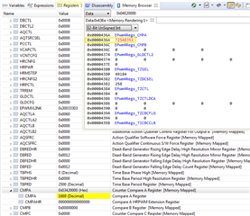
Configuring EPWM module CMPB for compare UP/DN counts loaded direct into period registers fails to load any value into CMPB of any configured generator.

Configuring dead band generators for mode 2 ACH/ACL complementary (Fig.18-8) is not possible via DBCTL[POLSEL] as typedef enumerations were missing epwm.h or hw_epwm.h. 

Note: I attempted to add enumerations below but polarity bits S2, S3 when made 2, 3 respectively caused load FED mode register bits to change. There are overlaps in the register control function calls that would be less confusing to separate (mode/polarity) register loads into two functions. The shift/mask enumeration values differ for the complementary dead band mode 2, versus mode 4 so the older C2000 firmware function call is not working as it should for mode 2 dead band control.  Closest DBCTL register can be set (0x000A) from calls below.

Fullscreen
1
2
3
4
5
6
7
8
9
10
11
12
13
14
15
16
17
18
19
20
21
//*****************************************************************************
//
//! Values that can be passed to EPWM_setDeadBandDelayPolarity(),
//! EPWM_setDeadBandDelayMode() as the \e delayMode parameter.
//
//*****************************************************************************
typedef enum
{
EPWM_DB_RED = 1, //!< DB RED (Rising Edge Delay) mode
EPWM_DB_FED = 0, //!< DB FED (Falling Edge Delay) mode
EPWM_DB_AHC = 1, //!< DB mode AH is Complementary
EPWM_DB_ALC = 0 //!< DB mode AL is Complementary
} EPWM_DeadBandDelayMode;
//*****************************************************************************
//
//! Values that can be passed to EPWM_setDeadBandDelayPolarity as the
//! \e polarity parameter.
//
//*****************************************************************************
typedef enum
XXXXXXXXXXXXXXXXXXXXXXXXXXXXXXXXXXXXXXXXXXXXXXXXXX

1. Why has the Instaspin SVM module code been embedded into ROM when it was shown in TRM and stated to be exposed for designer inspection?

2. Why is the CMPB register not being loaded with any count values via the SVM module in ROM given code below?

3. How can a (pair) of symmetric complementary (EPWM-A/B drive signals) ever be configured via ROM or firmware without configuring dead band mode 2 relative to SDK InstaSPIN FOC?

4. Why has C2000 register enumeration values (epwm.h etc..) not kept consistent binary/hex values that relate to TRM figures and register layouts? Instead C2000 firmware development has made it impossible for quick designer review using the TRM without entering CCS debug register view.   


Fullscreen
1
2
3
4
5
6
7
8
9
10
11
12
13
14
15
16
17
18
19
20
21
// setup the Counter-Compare Control Register (CMPCTL)
EPWM_setCounterCompareShadowLoadMode(obj->pwmHandle[cnt],
EPWM_COUNTER_COMPARE_B,
EPWM_COMP_LOAD_ON_CNTR_ZERO);
// setup the Action-Qualifier Output B Register (AQCTLB)
EPWM_setActionQualifierAction(obj->pwmHandle[cnt],
EPWM_AQ_OUTPUT_B,
EPWM_AQ_OUTPUT_HIGH,
EPWM_AQ_OUTPUT_ON_TIMEBASE_UP_CMPB);
//
EPWM_setActionQualifierAction(obj->pwmHandle[cnt],
EPWM_AQ_OUTPUT_B,
EPWM_AQ_OUTPUT_LOW,
EPWM_AQ_OUTPUT_ON_TIMEBASE_DOWN_CMPB);
// setup the Dead-Band Generator load mode Register (DBCTL)
EPWM_setDeadBandDelayMode(obj->pwmHandle[cnt], EPWM_DB_AHC_RED, true); //EPWM_DB_RED
EPWM_setDeadBandDelayMode(obj->pwmHandle[cnt], EPWM_DB_AHC_FED, true);
// select EPWMA as the input to the dead band generator
XXXXXXXXXXXXXXXXXXXXXXXXXXXXXXXXXXXXXXXXXXXXXXXXXX

  • There is something seriously wrong with epwm.h as it was coded does not set DBCTRL register bits properly for some modes. The mode table 18-9 does not make logical sense (red box/s) bit S8 must be 1 or S6, S7 can not be don't care at the same time. Anyway there is no way to configure DB control mode 2 for complementary High outputs on A/B channels or DBCTL=0xB. 

    Seemingly need an updated call that sets any one of the modes 1-7 shown in table 18-8. Otherwise the code as written does not allow DB mode 2 or to set S1, S0 with the correct binary value (0x3). The HWREG calls are impossible to determine what or why they refuse to set S0 to 0x1. We can only set 1 mode for complementary active high outputs but the code seems to argue both low and high active wave forms (Fig.18-34) can exist at the same time when that just ain't possible. 

    Mode 4 dead band is typically used for trapezoidal commutation. Seemingly SPV requires mode 2 or active high complementary signal pairs to each 1/2 bridge shown x49c TRM Fig. 18-34 (not shown below) 

  • Ok it was possible, mode 2 DBCTL=0xB but had to modify epwm.h with few ( |= ) on DBCTL writes or the bits were changing.

    Fullscreen
    1
    2
    3
    // setup the Dead-Band Generator load mode Register (DBCTL)
    EPWM_setDeadBandDelayMode(obj->pwmHandle[cnt], EPWM_DB_AHC_RED, true);//EPWM_DB_RED
    EPWM_setDeadBandDelayMode(obj->pwmHandle[cnt], EPWM_DB_AHC_FED, true);//EPWM_DB_FED
    XXXXXXXXXXXXXXXXXXXXXXXXXXXXXXXXXXXXXXXXXXXXXXXXXX

    Fullscreen
    1
    2
    3
    4
    5
    6
    7
    8
    9
    10
    11
    12
    13
    14
    15
    16
    17
    18
    19
    20
    21
    //*****************************************************************************
    //
    //! Values that can be passed to PWM_setDeadBandDelayPolarity(),
    //! EPWM_setDeadBandDelayMode() S4,S5 as \e delayMode parameter.
    //
    //*****************************************************************************
    typedef enum
    {
    EPWM_DB_RED = 1, //!< DB RED (Rising Edge Delay) mode
    EPWM_DB_FED = 0, //!< DB FED (Falling Edge Delay) mode
    EPWM_DB_AHC_RED = 1, //!< Rising Edge Delay for AH Complementary
    EPWM_DB_AHC_FED = 0, //!< Falling Edge Delay for AH Complementary
    EPWM_DB_MODE_AHC = 1, //!< DB mode2 is AH Complementary
    EPWM_DB_MODE_ALC = 0 //!< DB mode3 is AL Complementary
    } EPWM_DeadBandDelayMode;
    //*****************************************************************************
    //
    //! Values that can be passed to EPWM_setDeadBandDelayPolarity as the
    //! \e polarity parameter.
    XXXXXXXXXXXXXXXXXXXXXXXXXXXXXXXXXXXXXXXXXXXXXXXXXX

  • 1. Why has the Instaspin SVM module code been embedded into ROM when it was shown in TRM and stated to be exposed for designer inspection?

    2. Why is the CMPB register not being loaded with any count values via the SVM module in ROM given code below?

    3. How can a (pair) of symmetric complementary (EPWM-A/B drive signals) ever be configured via ROM or firmware without configuring dead band mode 2 relative to SDK InstaSPIN FOC?

    Only FAST estimator code is stored in the ROM. All of the other FOC codes include SVM are open source in the motorControlSDK and are independent of the device peripherals.

    You can refer to the codes in HAL_setupPWMs() in hal.c that configures the EPWM-A and B as a complementary output with dead-band, so the CMPB is not used for PWM. You might take a look at chapter 18.6 Action-Qualifier (AQ) Submodule about setting the AQCTLA to control the PWM output.

  • Only FAST estimator code is stored in the ROM. All of the other FOC codes include SVM are open source in the motorControlSDK and are independent of the device peripherals.

    Not exactly true: Only the calls to the handles are located in RAM/FLASH, for instance the SVM block binary coded sector lookup table is no where to be found in svgen.h or svgen.c. There are no actual functions located in SPV control files, only handles to ROM functions. Values are being cast to ROM via handles named in the compiled Symbols table.  I really don't see where CMPA is being loaded in any file since it seems to originate in ROM. That greatly limits the ability of designers to control the EPWM module order to maximize the speed torque curves of any motor!

    You might take a look at chapter 18.6 Action-Qualifier (AQ) Submodule about setting the AQCTLA to control the PWM output.

    Posted above figure and the SDK V2.01 was setting DBCTL polarity bits S3,S2 0x0. In order to get active high complementary outputs from dead band generators need to make EPWM_setDeadBandDelayPolarity(0, 2). And EPWM_DB_POLARITY_ACTIVE_HIGH = 0 makes EPWM-A/B signals AH but not complementary, especially since CMPB was disabled Fig.18-34  

    so the CMPB is not used for PWM

    Yet dead band mode 4 being enabled during power mode looses energy, mode 2 dead band is much better less low speed vibration motor is much quieter. 

    How can SW manipulate DBCTL register as to disable RED or FED only when a specific switch turns off? And allow CMPB to pass through dead band as to switch LOW side MOSFETS near saturation or (slow current decay)? That in my opinion will end the 1/2 wave current pulses entirely, symptoms of fast current decay. We do pass through CMPB cycles for trapezoidal FOC and it gains excellent speed over SPV.     

  • GI is there any specific EPWM configuration I can help with?

  • Hi Nima,

    The problem reported, epwh.h has a few register over writes of previous binary contents on 2nd call to same function, changing the DBCTL register control mode. This register overwrites require ( |= ) versus (=) asserting HWREG writes or loose previous contents, have a look above.

    Technically dead band mode 4 Active High (AH) was expected to be mode 2 (AHC) complementary. Also required adding a new enumeration for the polarity/mode function 0x2. After fixing delay mode function calls adding new enumerations, DBCTL register is now 0x000A (AHC) versus 0x0003 (AH). Minor fix but added some improvement in EPWM signal DSP being more robust.

    GI is there any specific EPWM configuration I can help with?

    Regarding CMPB the SDK v2.1 SVM transform does not load any value into CMPB as configured above code snips. I was attempting to configure an AHC asymmetric PWM generator pair and that requires CMPB to be static loaded for a fixed duty cycle. Also requires DB mode 2  with S4,S5 mode change, see TRM Fig.18-33. This type of asymmetric DSP mode produces slow current decay in high side MOSFETS typical of trapezoidal FOC commutation.

    The EPWM module via AHC dead band still produces 1/2 wave current pulses on the ends of  PWM full cycles. Do you think asymmetric PWM can arrest 1/2 wave current cycles from being developed or is something else causing them? I'm not a big fan of period direct load register writes, can that lead to this 1/2 wave current pulses being described? Yanming does not seem to get what I'm describing is/was seemingly a defect in Instaspin FOC SDK performance. 50% of the time issues are related to module configuration and the other 50% SW. 

    Red boxes CH2 are 1/2 wave pulses cause motor to crash into acceleration trajectory never to reach rated speed. This capture CH1 represents fast decay PWM mode. Seemingly EPWM needs CMPB nearly 100% duty cycle to generate (slow decay) sinusoidal waves (red boxes). How CH1 PWM produced inductive sine wave is amazing but lacking consistent sinusoidal current generation CH2. Seemingly that was not the intent of the Instaspin motor FOC and EPWM can produce robust sinusoidal inductive current at all times even from lower duty cycles. 

  • The problem reported, epwh.h has a few register over writes of previous binary contents on 2nd call to same function, changing the DBCTL register control mode. This register overwrites require ( |= ) versus (=) asserting HWREG writes or loose previous contents, have a look above.

    Which registers?

  • Which registers?

    EPWMx DBCTL bits S3, S2 as the text explains were being over written on second call assert, not preserving the previous write. 

    What about the CMPB load issue?

    I also enable shadow mode to time base PRD load zero count. Added PWM period shadows for 3 PWM generators (zero load) with little change in the 1/2 bridge output but did get a bit stronger current cycles wider band width. The PWM wave CH1 is now with less DC noise and Perhaps configuring Global updates CMPA could further improve the DSP.

    Seemingly x49c CCS debug GEL file is missing shadow load registers for the EPWMx generators. It would be great to see the shadow values being updated on zero PRD by the shadow load values. Oddly the CMPSSx have shadow registers for DACAVALA/B registers, why not the EPWMx generators. No need to answer just an observation.

  • BTW capture below is what trapezoidal fast decay PWM look like. See the similarity to CH1 above?


  • For the CMPB, if the SDK code doensnt update the CMPB, what is the value in CMPB register?

  • Hi Nima,

    if the SDK code doensnt update the CMPB, what is the value in CMPB register?

    0x0000

  • Does it look like capture red boxes are proper modulation CH1 to produce full sinusoidal inductive current CH2? It's hard to determine that question  via 2 channel scope Cold sweat 

  • Perhaps we don't need CMPB as EPWMx TBPRD counter register is matching time base multiples of compare counts CMPA 0x4E2/1250. Might explain the extend cycles of  periods (red boxes) on the ends? Zeroes do matter and do add up in hexadecimal counts.

  • Perhaps we don't need CMPB as EPWMx TBPRD counter register is matching time base multiples of compare counts CMPA

    GI,

    That seems correct. If the application code is not using CMPB, it must not be necessary especially if the register reads 0x00. Also sometimes the deadband module controls EPWMB by using EPWMA as the source.

    Nima

  • matching time base multiples of compare counts CMPA

    Perhaps you didn't see the memory mapped CMPA count register is 16x the value of CMPA match count and TBPRD. The count has appended 16 bits left shifted << the contents, the real TBPRD count is loaded 2500. Why is the memory mapped CMPA decimal count 16x higher than the matched CMPA value?

  • No change to very high CMPA memory mapped count even when period load is selected. Other type PWM memory mapped CMPA count go to zero and count starts over. The action qualifier output A on CMPA up and down counts. The period count is 2500 and the loaded CMPA match is 1250 decimal.

    Fullscreen
    1
    2
    3
    4
    5
    6
    7
    8
    9
    10
    11
    12
    13
    14
    15
    /* set comparator control load mode for default shadows CMP-A or B */
    EPWM_setCounterCompareShadowLoadMode(obj->pwmHandle[cnt],
    EPWM_COUNTER_COMPARE_A,
    EPWM_COMP_LOAD_ON_CNTR_PERIOD);
    // setup the Action-Qualifier Output A Register (AQCTLA)
    EPWM_setActionQualifierAction(obj->pwmHandle[cnt],
    EPWM_AQ_OUTPUT_A,
    EPWM_AQ_OUTPUT_HIGH,
    EPWM_AQ_OUTPUT_ON_TIMEBASE_UP_CMPA);
    EPWM_setActionQualifierAction(obj->pwmHandle[cnt],
    EPWM_AQ_OUTPUT_A,
    EPWM_AQ_OUTPUT_LOW,
    EPWM_AQ_OUTPUT_ON_TIMEBASE_DOWN_CMPA);
    XXXXXXXXXXXXXXXXXXXXXXXXXXXXXXXXXXXXXXXXXXXXXXXXXX
     

  • Thats the combination of CMPA + CMPAHR.

    CMPA left shifted + CMPAHR

  • Just look at the CMPA not the combined CMPA (large value)

  • Who on earth would ever know that by what GEL file has loaded. But still the memory mapped value never resets to zero or counting up on CMPA match counts.

  • the memory mapped value never resets to zero or counting up on CMPA match counts

    I'm not following. What is not counting up?

  • Yet CMPAHR registers are all disabled, So shifting left 16 bits seems to confirm high order byte CMPA match counts are occurring against the TBPRD module at higher counts then actually loaded. The single period are correct (50µs) but the cycle is longer than it should be. The extra undesired 1/2 wave pulses (red boxes) have to originate from some where. The phase current is supposed to be sinusoidal for the full TBPRD cycle, no interruptions as occurs.

    Note the wide breaks between EPWM module A output CH1 is not consistent to industry standard 3 phase sinusoidal current generation. The phase control registers PHSEN were all disabled SDK v2.01 motion FOC but TRM Fig.18-67 shows only EPWM1 CTR zero, NO Synci. I added change below synci, synco for EPWM 2,3 modules and still no change in the match counts CMPA. The memory mapped CMPA register should not free run in up counts, when CMPA match occurs the count should stop and count down to zero. The emulation mode control is only for CCS debug standby free run time, not execution time. So we should see the memory mapped CMPA count up and back down with TBPRD. 

    CMPA other configurations:

    Fullscreen
    1
    2
    3
    4
    5
    6
    7
    8
    9
    10
    11
    12
    13
    14
    15
    16
    17
    18
    19
    20
    21
    for(cnt=0;cnt<3;cnt++)
    {
    // setup the Time-Base Control Register (TBCTL)
    EPWM_setTimeBaseCounterMode(obj->pwmHandle[cnt],
    EPWM_COUNTER_MODE_UP_DOWN);
    // disable PHSEN bit in TB submodule
    EPWM_disablePhaseShiftLoad(obj->pwmHandle[0]);
    // enable PHSEN bit TBRD phase shifted load by TBHRS counts
    EPWM_enablePhaseShiftLoad(obj->pwmHandle[1]);
    // enable PHSEN bit TBRD phase shifted load by TBHRS counts
    EPWM_enablePhaseShiftLoad(obj->pwmHandle[2]);
    // set the period load mode quiet shadow loading /
    EPWM_setPeriodLoadMode(obj->pwmHandle[cnt], EPWM_PERIOD_SHADOW_LOAD); //EPWM_PERIOD_DIRECT_LOAD
    // set EPWM1 Master Sync Out pulse counter is zero and
    // set EPWM2, EPWM3 Slaves Sync pulse In/Out PWMxSYNCI/O.
    EPWM_setSyncOutPulseMode(obj->pwmHandle[0], EPWM_SYNC_OUT_PULSE_ON_COUNTER_ZERO);
    EPWM_setSyncOutPulseMode(obj->pwmHandle[1], EPWM_SYNC_OUT_PULSE_ON_EPWMxSYNCIN); //EPWM_SYNC_OUT_PULSE_ON_SOFTWARE
    EPWM_setSyncOutPulseMode(obj->pwmHandle[2], EPWM_SYNC_OUT_PULSE_ON_EPWMxSYNCIN);//EPWM_SYNC_OUT_PULSE_ON_SOFTWARE
    XXXXXXXXXXXXXXXXXXXXXXXXXXXXXXXXXXXXXXXXXXXXXXXXXX

  • CMPA in the registers view is:

    CMPA            combined version of CMPA and CMPAHR (the decimal value is not the the actual fractional value of the total CMPA with CMPAHR

         CMPA       actual value of the CMPA

         CMPAHR  

  • What is not counting up?

    That's all it ever does there is no change when the CMPA match action event, until pausing CCS debug. That may be an emulation issue making it seem that TB module is not synchronous with counter compare sub module. I expect the memory mapped count and CMPA count value only latches when match occurs TRM Fig.18-18 and Fig.16-68.

    How else can we verify CMPA match to count is actually occurring via CCS debug?  

    Fullscreen
    1
    2
    3
    4
    /* set comparator control load mode for default shadows CMP-A or B */
    EPWM_setCounterCompareShadowLoadMode(obj->pwmHandle[cnt],
    EPWM_COUNTER_COMPARE_A,
    EPWM_COMP_LOAD_ON_CNTR_PERIOD);
    XXXXXXXXXXXXXXXXXXXXXXXXXXXXXXXXXXXXXXXXXXXXXXXXXX

  • Just look at the CMPA not the combined CMPA (large value)

    Oddly we switch to decimal view for CMPA memory mapped GEL cell and the value is not only <<10, the TBPRD count value is extremely high. Sorry, forgot to mention that Weary.

  • No the value immediately gets set in the register. But it will be shadowed to an active register that is NOT shown to users when the event occurs.

  • No the value immediately gets set in the register

    The problem seems to be CMPA counter compare register bits exist high order Dword (<<10) unrelated with memory mapped counts TBCTR register. The EPWM_setCounterCompareValue() call adds 0x1 to the offset address. So CMPA 0x6A effectively offsets 0x6B? 

    Perhaps CMPA compare should shift the results (<<10) to compare memory mapped TBCTR counts with CMPA high order Dword bits or is that assumed? 

    Fullscreen
    1
    2
    3
    4
    5
    6
    7
    8
    9
    10
    11
    12
    13
    14
    15
    16
    17
    18
    19
    20
    21
    //
    // Get the register offset for the Counter compare
    //
    registerOffset = EPWM_O_CMPA + (uint16_t)compModule;
    //
    // Write to the counter compare registers.
    //
    if((compModule == EPWM_COUNTER_COMPARE_A) ||
    (compModule == EPWM_COUNTER_COMPARE_B))
    {
    //
    // Write to COMPA or COMPB bits
    //
    HWREGH(base + registerOffset + 0x1U) = compCount;
    }
    else
    {
    //
    // Write to COMPC or COMPD bits
    //
    XXXXXXXXXXXXXXXXXXXXXXXXXXXXXXXXXXXXXXXXXXXXXXXXXX

  • Decimal view of TB count indicates the entire 32 bits are being used for the TBCTR counts (CMPA, CMPB) low resolution register contents located in the high order Dword. The period load is only 2500 but memory mapped decimal counts of (TBCTR) register for CMPA have excessively high compares from combining high/low order Dwords of the memory mapped CMPA. 

    The actual TBCTR compare value depends on the instruction decodes of the memory mapped register. Seemingly CMPA compares the memory mapped count of TBCTR since 16 bit word register remains for the most part a steady state value. 

  • GI,

    Again the decimal fortmat should be used on the 

    CMPA

              CMPA -> this one

    NOT THE COMBINED CMPA register. The CMPA bitfield

  • Again the decimal fortmat should be used on the

    Perhaps you actually meant to type 32 bit decimal value should (NOT) be used CMPA.  Agree But...

    However the memory mapped count from TBCTR is 24 bits into (CMPA), the count being compared.  Seems to explain >170ms EPWM-A/B low state signal voids (capture CH1, CH2). The Instaspin PWM interrupt decimation time (328µs), scope measured via GPIO port.

    How can there be No PWM pulses >170ms void space unless the TBCTR 24 bit value is being compared to CMPA. CMPA 16 bit register value remains static in steady state power generation time. CMPA memory mapped decimal count should not be as high, HRPWM is/was not enabled! 

    Again the period is fixed (2500) counts 50µs, only the Pulse Width may vary dutycycle via CMPA updated load counts compared to TBCTR value. The CMPA compare surely seems to occur against 24 bit TBCTR memory mapped HRPWM decimal count. Note too Vsense EMF feed back to Clarke occurs inside the PWM void time, capture below figures.

    There is way to much dead air time in the EPWM generated outputs. As result the sinusoidal current wave form being generated CH2 has >170ms idle time in my steady state example. Note too TRM omits HRPWM registers detail for TB, TBCTR, CC sub modules. 

    Can you elaborate how >170ms PWM voids might otherwise be occurring as Instaspin interrupt decimation time is 328µs? 

  • Point being TB module TBCTR memory mapped CMPA register should not be counting >2500 when HRPWM was/is not enabled. Seemingly HRPWM mode is unknowingly enabled. One WA to reduce 24 bit memory mapped TBCTR running count to CMPA, >>10 the value via ASM patch.

  • if HRPE is 0 then it is not enabled.

  • if HRPE is 0 then it is not enabled.

    Wow x49c has 24 bit CMPA registers according to MCU datasheet, TRM figure above is dated. The original SDK v2.01 project was built using generic C28xx device tool chain. But change Lab5 tool chain TMS320F28049C noticed 170ms void issue and did not check the GEL versions on either CCS debug runs.


  • CMPA is 16 bits. Then CMPAHR most significant 8 bits.

    Together CMPA = CMPA + CMPAHR 24 bits total.

  • Agreed but the HRPE=0x0 not enabled so the 24 bit decimal TBCNT confuses 16 bit register match value, no matter CMPA +1U Bits 31-16 location.

    For a test I loaded CMPA value into Bits 15-0 and mem-mapped decimal count (1024) matched exactly the load value CCS debug but it only made EPWM-A state go high stay high. May try CMPAHR load values for match with 24 bit TBCTR values. That seems to be where count contention exists producing 170ms wide blank PWM cycles?

    It seems CMPA register location is reversed, CMPAHR should occupy bits 23-0 and CMPA bits 15-0, not the way it now exists. The 24 bit TBCTR count exceeds CMPA 16 bit load values by very large sum.

    Why does TBCTR default to a 24 bit wide count and CMPA only 16 bits wide, HRPE=0x0? Also only 16 bit wide load shown Fig.18-127 CMPA register not 24. Perhaps register layout was never update TRM to show HRPWM might ever do match counts via CMPAHR 24 bit updates? With TM4C TI family MCU registers 16 bit value existed 15-0 and 24 bits simply appends 8 bits to counter loads via bits 23-0. 

  • CMPA is 16 bits. Then CMPAHR most significant 8 bits

    TRM SPRUI33D – NOVEMBER 2015 – REVISED SEPTEMBER 2020 Fig.18-127 CMPA register does not properly convey to readers any such condition. EPWM module seems to default mode 4 (HRPWM) as TBCTR counts are 24 bits wide, CMPA load value bits 31-16 match count truncates? Seemingly TBPRD into counter compare sub module should not be allowed to exceed CMPA match count load values. That condition seems to add phantom periods to the CMPA match counts.  

  • You are correct the 24 bit is only applicable when HR mode is enabled.

  • only applicable when HR mode is enabled.

    Oddly the figures above indicate 24 bit CMPA and CMPAHR as +8 = 32 bits. Opposite of CMPA register Fig.18-127. That was the point I was trying to convey, an inconsistency exists. Counter compare sub module defaults 24 bit active bus, +8 is full 32 bits (uint_32t) CMPAHR in above figures.

    CMPA register x49c tool chain layout (2x16) does not indicate +8 structure exists. Determining TBCTR memory mapped read by visual compare of CMPA match count can not be determine via CCS debug.

    We can only determine TBCTR match occurs when CMPA value force loaded into low order bits (15:0). Then things get funky, 16 bit digital comparator match count logic fails to properly latch up/down action events. Low resolution CMPA bits should load (15:0) and high resolution 24 bits +8 adds to left of the first 16 bits for (23:0), total of 24 bits left to right in a 32 bit register, not two 16 bit registers.

    The tool chain + GEL file does not exactly match the datasheet register figure of counter compare sub module bus notations. It can't be loaded both ways, that is the point of contention, seemingly voids occur from unmatched count events. Yet the PRD is exactly 50µs with duty cycle and odd blanking voids 170ms. No DC blanking is enabled, only the edge count filter is enabled so doubtful 170ms voids from that.

  • No no, the CMPA standard is and always have been 16 bits. The HR added makes it 24 bits.

  • The HR added makes it 24 bits.

    The x49c is a updated type 4 EPWM module not type 0/1 of the older C2000 class. The x49c datasheet Fig.5-58 shows CMPA register and bus 24 bits wide, plus CMPAHR (+8) makes 32 bits register pair. The TRM Fig.18-127 is not the correct register layout for x49 MCU, and Fig.18-15 was also depicted for type 0/1 EPWM modules, the datasheet has highest priority showing type 4 EPWM module, not the TRM. If the device class tool chain was developed for type 0/1 it would explain how CMPA is being truncated causing incorrect PWM cycles and blanking intervals 170ms wide.

    Again PWM interrupt decimation 328µs loads of CMPA and 170ms EPWM-A pulse voids originate makes no logical sense! How can we discount what the actual x49 datasheet shows in Fig.5-58?

    The difference between type 0/1 and 4 EPWM module appears to be size of the internal data bus was expanded from 16 to 24 bits.

  • Yes on Type 4:

    CMPA standard is and always have been 16 bits. The HR added makes it 24 bits

  • This chapter guide is applicable for ePWM type 1. See the TMS320x28xx, 28xxx DSP Peripheral
    Reference Guide (SPRU566) for a list of all devices with an ePWM module of the same type, to determine
    the differences between the types, and for a list of device-specific differences within a type.T
    This chapter includes an overview of the module and information about each of its sub-modules:
    • Time-Base Module
    • Counter Compare Module
    • Action Qualifier Module
    • Dead-Band Generator Module
    • PWM Chopper (PC) Module
    • Trip Zone Module
    • Event Trigger Module
    ePWM Type 1 is fully compatible to the Type 0 module. Type 1 has the following enhancements in
    addition to the Type 0 features:

  • TMS320x28xx CMPA Bits 15:0 

  • EPWM type 4 seems to have 24 bit wide counter compare bus for a 24 bit register access HR mode. Typical to use 32 bit register pair to handle the additional 8 bits but the low CMPA 16 bits seems to be reversed in the x49c tool chain.

    Seemingly match counts CMPA are occurring at extremely high TBCTR counts. Seems to fit the 170ms blanking intervals between cycles of TB reloads.

  • Note CMPA bits (15:0) x49c tool chain GEL was moved into high order word (31:16) and is not fully aligned with TBCTR 24 bit wide bus.

    CMPA register Now loads to base address +1U. Seems to make CMPA match count only 8 bits wide. So there is a CMPA match count but not at the TBCTR count expected.

    Can we fix the GEL or tool chain to move CMPA input into bits (15:0) and CMPAHR (23:0)? Again removing base address (+1U) for writes CMPA (15:0) works as expected but TBCTR match counts go undetected. TBCTR shown as 24 bit wide and we can't logically squeeze CMPA active (24) loads into 16 bit wide TBTCR bus comparator type 4 EPWM module. 

  • Seems TBCTR counting 24 bit order as above logic figure (red box) shows CMPA 24 bits. It seems CMPA register being bits (31:16) lengthens the match counts cycle due to lower 15:0 appended counts into 32 bit fields. Perhaps it is possible to reduce TB output to be 16 bits for counter compare module CCM align closer to 15:0 TBDCTR counts? How can that be done?

  • 100% chance x49c tool chain is bugged if we trust the x49c datasheet or TRM. TBCTR is 24 bit wide bus and counts exceed TB load value 15:0 (2500) as indicated above CCS debug captures. I don't think making TBCTR register 16 bits is a logical WA, due to type 4 EPWM 24 bit bus issues. 

    That cause cascade failure CMPA being loaded into register bits (31:16). There is no overload MASK to stop 24 bit high TBCTR counts into CMPA 31:16. Below capture force loaded CMPAHR (15:0) with CMPA data as indicated x49c datasheet and TRM figures.

    Yet no TBCTR change is occurring bits (15:0) according to figures TB and CCM. The TBCTR bus is 24 bits wide (not 16 bits) so the tool chain and memory map do not agree. The TI tool chain WA is not working, captures indicate TBCTR count exceeds the loaded value of TB. Seemingly who ever made the x49c tool chain was unaware CMPAHR +8 bits was added into TBCTR output bus indicated by type 4 EPWM.

  • CMPA total register is 32 bits.

    The CMPA standards is 16 bits, followed by 8 CMPAHR bits. Followed by 8 reserved bits.

  • Seemingly x49c tool chain pushed CMPA into bits 31:16 when it should be in bits 15:0 as Type 4 EPWM module figures notes. The CMPA register is was memory mapped to 32 bit wide TBCTR counts. There is no bit mask shown in Fig.18-129 register view as might be expected for a 16+8 bit multi functional register. Some TI MCU have a prescale register to add 8 onto a 16 bit register, that does not exist in this x49c.

    CMPA was located register bits 31:16 when it should be located bits (15:0). Notice there is no TBCTR count in my last posted memory mapped image Bits 15:0. Further up posted image TBCTR is counting very high, 24 bits wide view via 32 bit integer in memory map address TBCTR.

    Perhaps masking a 24 bit memory mapped register via 16 bit Dword is not producing the intended results. TBCTR appears to be latching bits of CMPA located 31:16 producing incorrect comparator match events against time reference via TB period count of 2500,0000 when TBCTR max count is 2500 and not 32 bits wide.

  • Point being it may be more of an issue of how TBCTR is memory mapped into TB period counts. Notice above capture, 32 bit integer TBCTR count 72548352 exceeds 2500 maximum period. The PWM half period 1250 and TBCTR is in overflow to matched CMPA events. That seems to occur since CMPA was located 31:16 thus allows TBCTR to run into overflow time well above TB period counts.

1 2