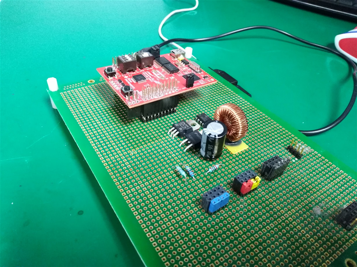
Other Parts Discussed in Thread: BOOSTXL-C2KLED, TMS320F28027, , TIDA-00282, CONTROLSUITE
Tool/software: Code Composer Studio
Hello I was trying to change the feedback of one of the booster converter of BOOSTXL-C2KLED from constant current to the output voltage divider.
Boosters 1-2 (GRN and BLU) are still using the old feedback at A2 and A1. while booster 3 (RED), I plan to use the voltage divider at B4.
I have changed the connections as follows:
long    IrefNetBus3=0;             // used as address for Iref3
long    VrefNetBus3=0;             // used as address for Vref3 (new)
long    UoutNetBus3=0;             // used as address for Uout3
#pragma DATA_SECTION(CNTL_2P2Z_CoefStruct3, "CNTL_2P2Z_Coef");
struct CNTL_2P2Z_CoefStruct CNTL_2P2Z_CoefStruct3;

// Slew control
long    Iset1=0;                  // Control loop 1 target
long    Iset2=0;                  // Control loop 2 target
long    Iset3=0;                  // Control loop 3 target
long    Vset3=0;                  // Control loop 3 target (new)

long    Itarget1=0;               // Control loop 1 target adjusted for Slew rate
long    Itarget2=0;               // Control loop 2 target adjusted for Slew rate
long    Itarget3=0;               // Control loop 3 target adjusted for Slew rate
long    Vtarget3=0;               // Control loop 3 target adjusted for Slew rate (new)

// Variables for easier "human" use
int16    Gui_Vin=0;      //Q09
int16    Gui_Vout1=0;    //Q08
int16    Gui_Vout2=0;    //Q08
int16    Gui_Vout3=0;    //Q08
int16    Gui_Vout8=0;    //Q08
int16    Gui_Iset1=0;    //Q15
int16    Gui_Iset2=0;    //Q15
int16    Gui_Iset3=0;    //Q15
int16    Gui_Vset3=0;    //Q08 (new)
int16    Gui_Iout1=0;    //Q15
int16    Gui_Iout2=0;    //Q15
int16    Gui_Iout3=0;    //Q15

   // Boost 3 connections
    ADCDRV_1ch_Rlt11 = &AdcNetBus[11];            // (was below, just moved here)
    CNTL_2P2Z_Ref3 = &VrefNetBus3;                // point to Vref3 (edited)
    CNTL_2P2Z_Fdbk3 = &AdcNetBus[11];              // point to Vout3 (edited)
    CNTL_2P2Z_Coef3 = &CNTL_2P2Z_CoefStruct3.b2;  // point to first coeff of 1st loop
    CNTL_2P2Z_Out3 = &UoutNetBus3;                // point to 2P2Z Uout3
    PWMDRV_1ch_UpDwnCnt_Duty2 = &UoutNetBus3;

    // Voltage connections
    ADCDRV_1ch_Rlt3 = &AdcNetBus[3];     // (was above, just moved here)
    ADCDRV_1ch_Rlt9 = &AdcNetBus[9];
    ADCDRV_1ch_Rlt10 = &AdcNetBus[10];
    ADCDRV_1ch_Rlt12 = &AdcNetBus[12];

    // All Channel shut-down control (no sequencing)
    if(StopAll == 1)
    {
        IrefNetBus1 = 0;
        IrefNetBus2 = 0;
        IrefNetBus3 = 0;
        VrefNetBus3 = 0;
        ChannelEnable1 = 0;
        ChannelEnable2 = 0;
        ChannelEnable3 = 0;
        Gui_Iset1 = 0;
        Gui_Iset2 = 0;
        Gui_Iset3 = 0;
        Gui_Vset3 = 0; // (new)
        MergeLEDs = 0;
        AutoColor = 0;
        SetColor1 = 0;
        SetColor2 = 0;
        StopAll = 0;
    }

    // Channel 3 On/Off control
    if(ChannelEnable3 == 1)
        //Itarget3 = Iset3; // (was)
    	Vtarget3 = Vset3; // (is)
    else
        //Itarget3 = 0; // (was)
    	Vtarget3 = 0;  //(is)


    /* (was)
    SlewError = (IrefNetBus3 - Itarget3);
    if (SlewError > SlewStep3)
        IrefNetBus3 = IrefNetBus3 - SlewStep3;
    else if (SlewError < (-SlewStep3) )
        IrefNetBus3 = IrefNetBus3 + SlewStep3;
    else
        IrefNetBus3 = Itarget3; */

    // (is)
    SlewError = (VrefNetBus3 - Vtarget3);
    if (SlewError > SlewStep3)
        VrefNetBus3 = VrefNetBus3 - SlewStep3;
    else if (SlewError < (-SlewStep3) )
        VrefNetBus3 = VrefNetBus3 + SlewStep3;
    else
        VrefNetBus3 = Vtarget3;

    //Multiply with longs to get proper result then shift by 14 to turn it back into an int16
    Iset1 = ((long)Gui_Iset1*(long)iK_Iset) >> 5;
    Iset2 = ((long)Gui_Iset2*(long)iK_Iset) >> 5;
    Iset3 = ((long)Gui_Iset3*(long)iK_Iset) >> 5;
    Vset3 = ((long)Gui_Vset3*(long)K_Vout) >> 16; // (new, maybe wrong, but for experiment can see the raw data on the debug)


    /* (was)
    if((Gui_Iset3 == 0) && (AdcNetBus[3] == 0) && (UoutNetBus3 >= _IQ24(0.001))){
        AdcNetBus[3] = 40960;
    }
    */
    // (is)
    if((Gui_Vset3 == 0) && (AdcNetBus[11] == 0) && (UoutNetBus3 >= _IQ24(0.001))){
        AdcNetBus[11] = 40960;
    }
And here is the result when in debug:
| Duty2 | long | 0.0 (Q-Value(24)) | 0x00008850@Data |
| Gui_Iout2 | int | 0.00494385 (Q-Value(15)) | 0x0000881E@Data |
| Gui_Vout2 | int | 23.8633 (Q-Value(8)) | 0x00008822@Data |
| Gui_Iset2 | int | 0.00497437 (Q-Value(15)) | 0x00008816@Data |
| IrefNetBus2 | long | 126447 | 0x00008864@Data |
| UoutNetBus2 | long | 0.2317534685 (Q-Value(24)) | 0x00008860@Data |
| Hist_Vout2 | long[8] | [1223,1219,1224,1222,1220...] | 0x00008950@Data |
| Duty3 | long | 0.0 (Q-Value(24)) | 0x0000884C@Data |
| Gui_Iout3 | int | 0.0 (Q-Value(15)) | 0x00008821@Data |
| Gui_Vout3 | int | 11.3047 (Q-Value(8)) | 0x00008823@Data |
| Gui_Iset3 | int | 0.0 (Q-Value(15)) | 0x00008819@Data |
| Hist_Vout3 | long[8] | [572,588,579,582,588...] | 0x000088E0@Data |
| Vtarget3 | long | 1198 | 0x00008828@Data |
| Vset3 | long | 1198 | 0x00008836@Data |
| Gui_Vset3 | int | 15.0 (Q-Value(8)) | 0x00008818@Data |
| VrefNetBus3 | long | 1198 | 0x00008852@Data |
| UoutNetBus3 | long | 0.0 (Q-Value(24)) | 0x00008854@Data |
| AdcNetBus | long[16] | [0,0,135168,0,0...] | 0x00008980@Data |
| CNTL_2P2Z_CoefStruct3.b2 | long | 327680 | 0x00008A4E@Data |
| AdcNetBus[11]>>12 | long | 571 | |
| AdcNetBus[10]>>12 | long | 1224 |
Is it possible to change the feedback pins or something missing in my code?


