This thread has been locked.

If you have a related question, please click the "Ask a related question" button in the top right corner. The newly created question will be automatically linked to this question.

CCS / TMS570LS0232:TMS570LS0232 nerror and PWM questions

Part Number: TMS570LS0232
Other Parts Discussed in Thread: HALCOGEN

Tool/software: Code Composer Studio

Hi ALL,

I have some questions about using TMS570 for BMS

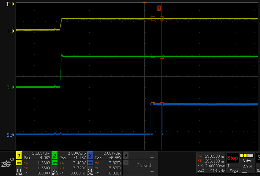
1.I found it in the safety Handbook. TMS570 after the completion of the electrical self-test, will be through the nerror foot output a low pulse, and the actual measurement of output of 2 low pulse, I would like to ask whether this is normal, which Yellow line for 1.2V power supply, Green Line for 3.3V power supply, Blue line for the nerror output. is the external circuit to the TMS570 self-test after the output of this nerror to do testing, not to do the test to meet the safety design requirements?

2.I see in the datasheet that ADC has two kinds of self-test, normal self-test and median self test. The functions produced by Halcogen correspond to void Adccalibration (adcbase_t *adc) and UInt32 adcmidpointcalibration (adcbase_t *adc), respectively, Excuse me these 2 kinds of self-test way is to use only one or two kinds of use, in the use process what request?

3.I am in Halcogen configuration PWM capture, choose black box mode, what is the principle of this mode to achieve capture? Not found in the reference manual.

invoking void Capgetsignal (hetrambase_t * hetram, UInt32 cap, hetsignal_t *signal) in a Halcogen-generated drive can achieve PWM capture, change the PWM duty ratio, and achieve dynamic capture. When the PWM signal input is removed, the function is called to find the period and duty ratio or the value before the PWM input is disconnected. How does this work out?

  • Hello Huang,

    1. Do you mean efuse self-test? If an error occurs during the eFuse controller self test, then a group 1 channel 41 error and a group 1 channel 40 error are sent to the ESM. After reset, by default, the group one errors do not affect the ERROR pin. If the software enables the appropriate bit in the appropriate ESM Influence Error Pin Set/Status Register (ESMIEPSRn) while the group one error is set, the ERROR pin will go low. 

    2. ADC module supports a self-test mode. The self-test is used to detect an open or a short on the ADC input channels. The calibration feature is used to calibrate ADC module with the corrected error offset. You can use either adcCalibration(..) or adcMidpointCalibration(..). 

    3. NHET is used to generate PWM or capture input PWM signal. Please refer to the NHET chapter (High-End Timer (N2HET) Module) of the TRM. The following simple NHET microcode can generate a simple PWM signal at NHET pin 0:

    L00 CNT { next= L01, reg=A, irq=OFF, max = 4 }
    L01 ECMP { next= L00, cond_addr= L00, hr_lr=LOW, en_pin_action=ON, pin=0, action=PULSEHI, reg=A, irq=OFF, data= 1, hr_data = 0x0 }

    The period of the PWM is defined by the max value in CNT instruction, and the duty cycle is determined by the values of data and hr_data in ECMP intsruction.

  • Hi QJ Wang,

    Regarding the PWM problem, when the PWM connection is disconnected unexpectedly, the PWM does not report the error, will upload the data before the connection, may I ask this to solve?

  • Hello Charles,

    If the PWM signals are disconnected externally, you will not get an error report unless you have a PWM detection mechanism outside the MCU (for example, capture the PWM signal at another NHET pin).

    The content in NHET memory will not be cleaned until the CPU is reset or cleaned manually. Every time when you reset teh MCU, it will initialize the NHET module and copy the NHET microcode to the NNET RAM, then NHET microcode in NHET RAM will be executed immediately after the GCR register is SET properly.
  • Hi QJ Wang,

    Thanks, understand
    The first problem I had before was that it was normal for me to detect two low signals at the NERROR feet when I turned on.