This thread has been locked.

If you have a related question, please click the "Ask a related question" button in the top right corner. The newly created question will be automatically linked to this question.

EVM430-F6779: THD implementation

Part Number: EVM430-F6779
Other Parts Discussed in Thread: MSP430F6779, UNIFLASH, MSP430F67791A, TIDM-THDREADING

Hello,

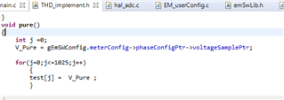
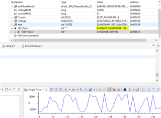
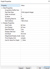
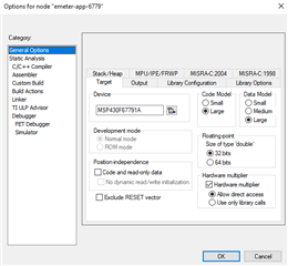
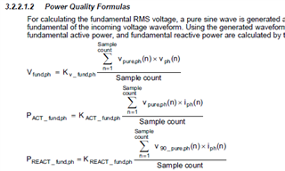
 I want to implement THD measurement for the evm430-f6779 energy meter board. The THD measurement was implemented in IAR but not in EMDC generated CCS programs. I am finding it difficult to implement it for my board. As per the document I generated a pure sine wave which would be used for fundamental RMS voltage calculation using iqsine method with 256 samples per quadrature signal( i.e. 1025 samples in all).

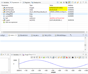
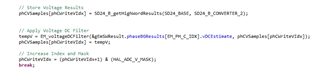
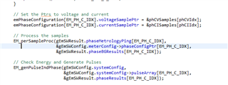
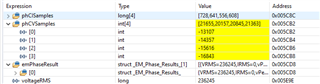
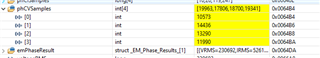
And according to the following section, for fundamental RMS voltage calculation we require Vpure and Vph of which Vpure has been generated but I am not able to find how to acquire Vph from the program. In hal_adc.c the raw adc data is fed to voltageSamplePtr but that doesn't seem useful. I am not able to get the raw adc data which is being calculated properly.

Please suggest some ways to resolve this problem. In other words how to evaluate fundamental rms voltage?

Thanks 

Avinash

  • Hello Avinash,

    Unfortunately, the support provided in this previous thread  is as much support as we can give at this time on this subject. 

  • Hello Sir ,

    Thank you for response. According to previous thread I did understand how to generate a sine wave for generating fundamental voltage but I was facing difficulty in procuring the voltage samples from the hal_adc program.

    The following image shows the snipet of code used to store voltage samples:

    And the following voltage samples are being sent to a voltage sample ptr as follows:

    The following results in pointer are being used to calculate other important parameters like RMS, peak to peak etc. Now for evaluating fundamental rms voltage I am trying to get these samples but I am not able to get a sinusoidal voltage samples. The phCVSamples[phCWriteVIdx] array has a size of 4 and the following array keeps changing. How could I get sinusoidal voltage sample (tried to store sample in different array but that changes evaluation parameters) so that I could use it for fundamental rms voltage? Also the following samples collected in this array doesn't seem to be in sinusoidal pattern as I am observing frequent sign changes.

    Following are results of phCVSamples[phCWriteVIdx] 

    Also could I get a tip or suggestion on how I could proceed further from the following step to calculate fundamental rms voltage.

    1. I generated the pure sine wave for fundamental voltage by creating 1024 samples of iqsine with amplitude == 32767.
    2. I did try to observe the voltageSamplePtr which is being used to store voltage results but it doesn't give me a sinusoidal voltage signals when I observe in graph.

    Sorry for the inconvenience, I have been stuck here and needed some help.

    Thanks

    Avinash 

  • Hello,

    So I wanted the voltage samples the sd24 is taking and storing them in voltageSamplePtr. So I created another variable to plot its graph or observed them in watch window and the results are as follows:


    Please suggest where I am going wrong. I want the sinusoidal samples of voltage signal being sent to adc of controller.

    Thanks

    Avinash

  • Hello Avinash,

    As stated before, no additional support on this topic can be given by TI. This thread will remain open in case other community members would like to chime in around your inquiry. 

  • Hello,

      Thank you for your response.

    Is there any other way I could implement THD measurement then. I found this TIDMTHDREADING-1.0 (IAR based) provided by ti which supports thd measurement but how should I compile it to program the microcontroller. When I try to build and compile it gives me an error of "Error[Og008]: Code size limit exceeded. 12 278 code bytes is more than the limit of 8 192 bytes". No build file was pre included to program the controller.

    Also my controller is MSP430F67791A and not MSP430F6779 and thus, this gives me an error when I try to flash other IAR programs for this evm via uniflash. Any way I could resolve this too. 

    Thanks 

    Avinash

  • When I try to build and compile it gives me an error of "Error[Og008]: Code size limit exceeded. 12 278 code bytes is more than the limit of 8 192 bytes".

    Do you have a full IAR license, or are you using a "code size limited" IAR KickStart license?

    See Code size limitation persist for some possible reasons for this error.

  • Hello, 

    Previously I was using IAR KickStart license and hence I was getting the code size error before but now I have the IAR full version and now the code is building properly.

    In the TIDM GUI folder it was suggested to use GUI associated to an i2040 SLAA637 application note software in which three files were present:

    Do we have to configure the GUI for evm430f67791?

    Which of the following is the suggested one for three phase evm430f67791 energy meter for THD measurement?

    I installed the 2nd file and configured the GUI xml file for the given port. But when I turn on the power it does not detect the evm. (currently I am only sending phase C voltage to the controller and not connecting the rest).

    How can I make THD measurement work? I did a " rebuild all " instruction to all the files in IAR in order and then executed the " Download and debug " instruction in IAR and then stopped it.

    When I connect the C phase voltage and the rs232 interface with computer, the GUI does not detect the evm?


    Thanks 

    Avinash

  • Hello,

      So now instead of implementing THD through CCS I am now trying to implement using the TIDM thdreading source code provided by Ti for THD measurement. The following codes are implemented in IAR software thus I installed IAR free trail version to test it out.

    For the following I had few doubts:

    • My controller is msp430f67791a and not msp430f6779, so will the source code be compatible with the following controller? How ever I tried to configure some settings for f67791a and the program was running properly in debug mode. Following is the configuration I did : 

    • As per the instructions for GUI, I downloaded the following file which included three installers of which I installed one of them.

    • So after debugging the following program ( before rebuilding all files successfully), I connected a voltage source to only one channel i.e. SD2 pin and tried to observe for results but the GUI didn't connect i.e. stayed red even when the controller was given power. How to do the configuration?
    • Also, will the code work with only one phase connected for testing purpose?

    Thanks,

    Avinash

  • Avinash,

    Please see the following application note for differences between the "A" and "non-A" versions of this device. Although the same base device, there are significant changes made the the "A" version of the device. This may need to be accounted for in what you are doing. 

    Please see sections 4/5/6 within the TIDM-THDREADING for details on setting up the EVM for proper operation. 

    Unfortunately, there is no longer additional documentation available on how to use this older GUI and library as it is no longer actively supported. 

**Attention** This is a public forum