This thread has been locked.

If you have a related question, please click the "Ask a related question" button in the top right corner. The newly created question will be automatically linked to this question.

MSP-EXP430FR5969: I2C SCL line behavior after address byte

Part Number: MSP-EXP430FR5969

Hi,

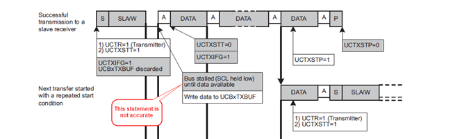
I have a question about the expected behavior of the SCL line after transmitting the slave address and before putting any data on the TXBUF.

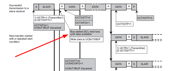
In the source code (below), I am simply transmitting the slave address and then going into an infinite loop. It is my understanding (based in the datasheet) that this code will cause the MSP430 to hold the SCL line low indefinitely after the transmission of the slave address and the R/W bit. I see this behavior occurring when addressing one of the slave devices (address 0x08) but not the other slave device (address 0x10). Please see test code 1 and test code 2.
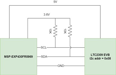
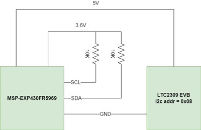
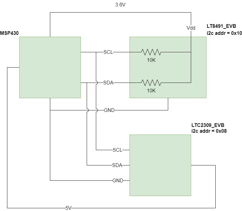
Circuit schematic:

Test code 1 (UCB0I2CSA   =  0x10):

#include <msp430.h>

void main (void)
{
    WDTCTL  = WDTPW | WDTHOLD;          //Disable internal watchdog timer
    P4DIR   |= BIT6;                    //Configure P4.6 as an output (for debugging on the scope)
    P1SEL1  |= (BIT6|BIT7);             //Configure P1.6 (SDA) and P1.7 (SCL) for i2c functionality
    PM5CTL0 &= ~LOCKLPM5;               //Clear the LOCKLPM5 bit so previous settings take effect

    //Configure the i2c peripheral
    UCB0CTLW0 |= UCSWRST;               //Hold USCI module in reset
    UCB0CTLW0 |= ( UCMST | UCMODE_3 );  //I2C master mode
    UCB0CTLW0 |= UCSSEL__SMCLK;         //Use SMCLK (1MHz)
    UCB0BRW    = 10;                    //Divide SMCLK by 10 to achieve 100KHz baud rate
    UCB0CTLW0 &= ~UCSWRST;              //Pull USCI module out of reset

    //delay (each cycle is  1us)
    __delay_cycles( 3000000 );          //Delay to give me time to trigger the scope

    P4OUT       |= BIT6;                //Set P4.6 high
    UCB0I2CSA   =  0x10;                //Set slave address (0x64 => LTC2943, 0x10 => LT8491, 0x08 => LTC2309)
    UCB0CTLW0   |= UCTR;                //Set I2C bus in transmit mode
    UCB0CTLW0   |= UCTXSTT;             //Issue START condition (start + i2c_address + RW bit)

    //Infinite loop
    while(1)
    {
        //Read the UCSCLLOW bit and control P4.6
        if(  UCB0STATW & UCSCLLOW )
        {
            P4OUT &= ~BIT6;     //If UCSCLLOW is set, clear P4.6
        }
        else
        {
            P4OUT |= BIT6;      //If UCSCLLOW is cleared, set P4.6
        }
    }

} //main()

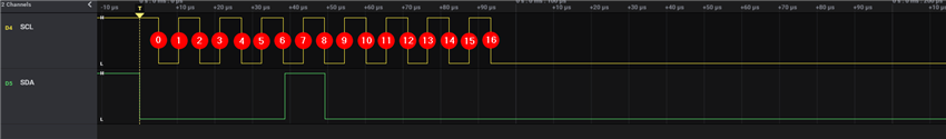
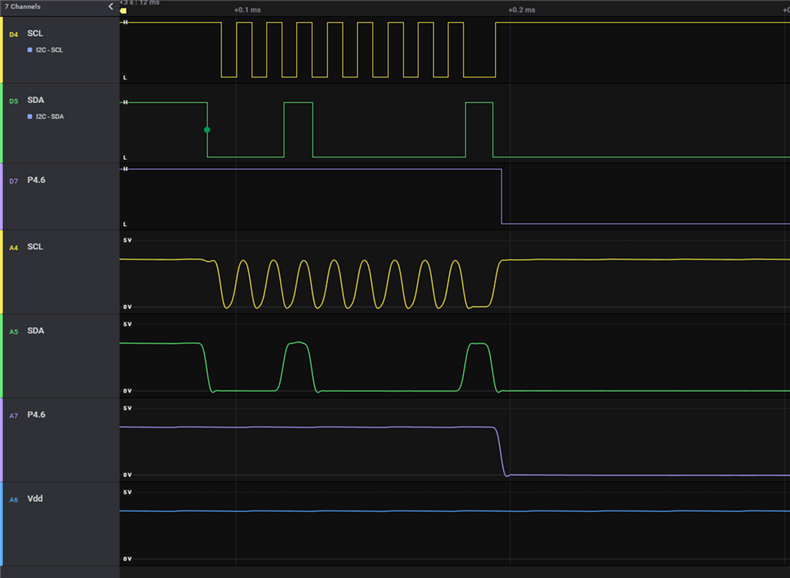
Digital and analog capture of test code 1 (addressing 0x10 slave device):

Notice how SCL line clocks 9 times and then holds high. This is NOT expected behavior. Why does the MSP430 release the SCL line here!?

Test code 2 (UCB0I2CSA   =  0x08):

#include <msp430.h>

void main (void)
{
    WDTCTL  = WDTPW | WDTHOLD;          //Disable internal watchdog timer
    P4DIR   |= BIT6;                    //Configure P4.6 as an output (for debugging on the scope)
    P1SEL1  |= (BIT6|BIT7);             //Configure P1.6 (SDA) and P1.7 (SCL) for i2c functionality
    PM5CTL0 &= ~LOCKLPM5;               //Clear the LOCKLPM5 bit so previous settings take effect

    //Configure the i2c peripheral
    UCB0CTLW0 |= UCSWRST;               //Hold USCI module in reset
    UCB0CTLW0 |= ( UCMST | UCMODE_3 );  //I2C master mode
    UCB0CTLW0 |= UCSSEL__SMCLK;         //Use SMCLK (1MHz)
    UCB0BRW    = 10;                    //Divide SMCLK by 10 to achieve 100KHz baud rate
    UCB0CTLW0 &= ~UCSWRST;              //Pull USCI module out of reset

    //delay (each cycle is  1us)
    __delay_cycles( 3000000 );          //Delay to give me time to trigger the scope

    P4OUT       |= BIT6;                //Set P4.6 high
    UCB0I2CSA   =  0x08;                //Set slave address (0x64 => LTC2943, 0x10 => LT8491, 0x08 => LTC2309)
    UCB0CTLW0   |= UCTR;                //Set I2C bus in transmit mode
    UCB0CTLW0   |= UCTXSTT;             //Issue START condition (start + i2c_address + RW bit)

    //Infinite loop
    while(1)
    {
        //Read the UCSCLLOW bit and control P4.6
        if(  UCB0STATW & UCSCLLOW )
        {
            P4OUT &= ~BIT6;     //If UCSCLLOW is set, clear P4.6
        }
        else
        {
            P4OUT |= BIT6;      //If UCSCLLOW is cleared, set P4.6
        }
    }

} //main()


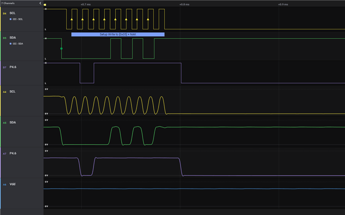
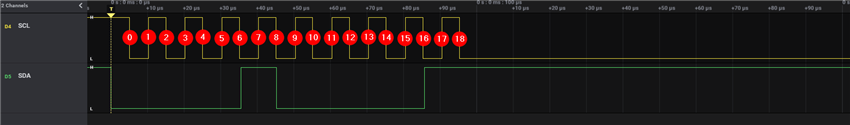
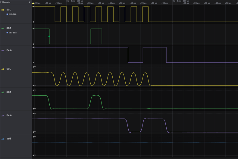
Digital and analog capture of test code 2 (addressing 0x08 slave device):

Notice how SCL line clocks 8 times and then is held low (indefinitely); this is expected behavior.

1. Why does the MSP430 not hold the line low when addressing slave device 0x10? (i.e. test code 1)

2. Slave device 0x10 may perform i2c clock stretching but I believe this should NOT prevent the MSP430 from continuing to hold the SCL line low. Is this correct? If not, please help me understand why that is the case.

3. What possible condition (hardware or software) can explain the behavior that I'm seeing with the SCL line in test code 1?

Thanks,

Aamer

  • It appears that in case one there is no ACK. The target should pull SDA low to ACK but see how it goes high? Many I2C devices have a pin with which to change a bit or two in the device address. Check your hardware to see what it is.

  • Hi David,

    Thanks for your reply.

    I know exactly the SDA pulse that you are referring to and I have studied and tested this closely a few days ago. I do not believe this is a 'no ACK' situation for the following reasons:

    - The ACK (or NACK) is read while the SCL line is high (I think this is in the i2c spec if I'm not mistaken). The SDA pulse that you are referring to occurs while the SCL line is low so it is a 'no factor'. I believe this pulse is occurring while the slave is stretching the SCL line low.

    - I am familiar with setting the i2c address on the slave device pins and I have confirmed that the pins are set correctly (address 0x10). I've even changed the address pins to something different and then matched that on my MSP430 code and still saw the same behavior.

    - I have monitored successful communication between this EVB and a PC tool made by the supplier. Even with successful communication, this pulse in the SDA line exist. It looks exactly the same (SDA pulses high while the SCL line is low).

    - I do not see a NACK flag being triggered on the MSP430 due to this pulse (I used different code to confirm that).

    - When I intentionally use a bogus i2c address (i.e. NACK condition), I see a completely different behavior (more details below).

    I believe that what is happening during this specific pulse that you are referring to is the following:

    1. MSP430 clocks slave address and R/W bit and then holds the SCL line low.

    2. Slave stretches the SCL line low.

    3. MSP430 releases SDA line (since the slave is not holding it low yet, it is pulled up by the resistor). This SDA pulse would not be read by the MSP430 because the SCL line is low.

    4. Slave pulls SDA line low to prepare for ACK'ing its address.

    5. Slave releases SCL line to then let the MSP430 take control of the SCL line. In this case, the MSP430 releases the SCL line and registers an ACK. What is baffling me is that the MSP430 should have not released the SCL line yet since I have not written anything to the TXBUF.

    But even if I am completely mistaken about my points above and this slave is hypothetically 'not ACK'ing' its address, then the SCL should still be held low until I issue a stop condition. I have just ran a test with the same circuit shown above and I simply changed the slave address in code to something bogus (0x05) and this is what the capture looks like: (notice how different it looks from test code 1 capture above):

    Cheers,

    Aamer

  • In idle state, SCL should be high.  You need check you firmware and hardware,  this link: msp430fr59xx_euscib0_i2c_10.c (ti.com) is for you to refer firmware.

  • Hi ,

    I am specifically discussing the situation where the MSP430 has just finished transmitting the slave address and is waiting for the next step. The MSP430 datasheet specifically mentions that the SCL line would be 'idling low' in this case. See the following diagram:

    Thanks,

    Aamer

  • I seem to have forgotten the practical aspect of this. What happens when you provide a byte to TXBUF in a timely fashion? Like normally happens.

  • Hi David,

    Good question... while the question may appear mostly academic, I believe there is some practical benefit in finding the answer.

    I want to understand the cause of this discrepancy (and timing requirements) so that I can make a better judgement regarding how I should write my i2c driver code. Sure, if I provide a byte in a timely fashion to the TXBUF, communication works ok. But this means that I can no longer use a polling architecture to run my i2c driver. Furthermore, it means that if the code changes a bit, timing would be off and we would see the problem happening again.

    We opted to use a rather non-traditional i2c driver in my other question (i.e. not interrupt based) in order to prevent possible bus lock-ups (e.g. getting into a situation where we are indefinitely waiting for an interrupt to trigger). The device that will use this i2c driver will end up in a very remote location where no firmware updates would be possible so I'd like to insure that I write a robust and fail-proof i2c driver.

    If the timing of how my code interacts with the USCI module on the MSP430 is critical (which it seems like it is), then I would need to re-write my original i2c driver using interrupts but then I think I should use a different timer interrupt to 'watch over' the i2c interrupts and make sure that nothing gets locked up.

    So to summarize, I would like to get a very clear understanding of the behavior of the i2c bus on the MSP430 so that I can write a robust i2c driver that can handle all possible anomalies and artifacts.

    I still don't quite understand why the SCL line is released by the MSP430 as shown in test code 1. Perhaps that short SDA pulse is confusing the MSP430 and making it falsely think that the slave is not ACK'ing or something along those lines?

  • This seems that it is the problem of your slave device.  You can try to change your slave address in Figure 1, and then observe the waveform of SCL SDA to see if there is ACK Signal

  • Hey guys,


    I think I may have finally figured out the root cause of this behavior. I have a suspicion that the MSP430 does not adhere to one of the rules of the i2c protocol. Specifically, I believe that the MSP430 is reading the value of the SDA line after the R/W bit and while the SCL line is still low (i.e. before the rising edge of the ACK clock cycle). Then based on the value of the SDA line at that timeframe, the MSP430 makes the decision to either release the SCL line high and clocking in the ACK/NACK bit or holding the SCL low until the TXBUF is written.

    Below is a very simple test setup that hopefully can illustrate this point. I hope that someone else can at least try this test and confirm/deny my finding if possible (you should be able to perform this test with any slave device).


    I have the following code running on the EXP-MSP430FR5969 EVB:

    #include <msp430.h>
    
    void main (void)
    {
        WDTCTL  = WDTPW | WDTHOLD;          //Disable internal watchdog timer
        P1SEL1  |= (BIT6|BIT7);             //Configure P1.6 (SDA) and P1.7 (SCL) for i2c functionality
        PM5CTL0 &= ~LOCKLPM5;               //Clear the LOCKLPM5 bit so previous settings take effect
    
        //Configure the i2c peripheral
        UCB0CTLW0 |= UCSWRST;               //Hold USCI module in reset
        UCB0CTLW0 |= ( UCMST | UCMODE_3 );  //I2C master mode
        UCB0CTLW0 |= UCSSEL__SMCLK;         //Use SMCLK (1MHz)
        UCB0BRW    = 10;                    //Divide SMCLK by 10 to achieve 100KHz baud rate
        UCB0CTLW0 &= ~UCSWRST;              //Pull USCI module out of reset
    
        __delay_cycles( 3000000 );          //Delay 3 seconds to give me time to trigger the scope
    
        UCB0I2CSA   =  0x08;                //Set slave address 0x08 is the address of the LTC2309
        UCB0CTLW0   |= UCTR;                //Set I2C bus in transmit mode
        UCB0CTLW0   |= UCTXSTT;             //Issue START condition (start + i2c_address + RW bit)
    
        //Infinite loop
        while(1);
    
    } //main()

    And I have this code run on two test circuits shown below.

    Test_A circuit:

    Test_B circuit:

    Notice that the only difference between the two tests is that in Test_B, the i2c lines are disconnected from the slave device which would obviously result in a 'no ACK' situation.

    Here are the digital captures of the i2c lines from Test_A and Test_B (I've numbered the edges of the SCL line for reference later).

    Test_A capture: (ACK condition)

    Test_B capture: (no ACK condition)

    Key Observations:

    • In Test_A (slave ACK's its addres), the SCL line clocks 8 times and is then held low indefinitely (per datasheet, the MSP430 is holding the SCL low until data is written to the TXBUF).
    • In Test_B (no ACK from slave), the SCL line clocks 9 times and is then held low indefinitely.

    The key question to ask here is: "After clock edge #16 in the pictures above, how does the MSP430 decide to either (a) issue the 9th clock cycle now or (b) wait until TXBUF is written before issuing the 9th clock cycle?"

    The only reasonable answer to this question is that immediately after edge #16 and while SCL is still low, the MSP430 reads the SDA line and performs the following check:

    "if the SDA line is high, MSP430 can release the SCL line high now (or soonish) to clock in the 9th clock cycle"

    "if the SDA line is low, MSP430 will hold the SCL line low until the TXBUF is written"


    If my reasoning above is correct, then this would mean that the MSP430 does not properly adhere to the i2c specifications. The MSP430 is reading the SDA line after edge#16 and before edge#17 (i.e. while the SCL line is low). This is a problem because the SDA line is not required to stabilize before/during this time period so the value of SDA line at this time period is unreliable and should be ignored. I2C data (including ACK/NACK bits) is read when the SCL line is high. Here are some excerpts from the i2c spec document (this link):


    This also explains the strange behavior I was seeing when talking to the LT8491 device which was the reason this whole issue got uncovered in the first place. The slave device (LT8491) was indeed sending a valid i2c ACK in accordance to i2c rules. The MSP430 was trying to read the ACK/NACK bit earlier than it is should have been. I hope we can agree on the fact that the LT8491 is sending a proper ACK back to the MSP430 this should be very easy to prove/disprove by comparing the scope captures in my previous messages to the i2c specification document.

    If my statements and findings above are not correct, then I think this is a fair question that deserves a good answer from the MSP430 experts:
    "After clock edge #16 in the pictures above, how does the MSP430 decide to either (a) issue the 9th clock cycle now or (b) hold SCL low and wait until TXBUF is written before issuing the 9th clock cycle?"


    If there are concerns that my tests were not setup correctly, then I imagine that this experiment can easily and quickly be replicated by someone else to proof/disprove my findings. I hope that this information can be used to improve future designs of the USCI/I2C module of the MSP430 and to also update the datasheet/errata to reflect this. At minimum, I hope that we can at least all agree that this following diagram is no longer accurate for all cases:

    Thanks for everybody's help and discussion on this item.

    Sincerely,

    Aamer

  • If you look again at the data capture in the first message in this thread you will see that clock stretching is not invoked by the target. Maybe.

    You set or clear P4.6 based on the state of UCSCLLOW. This gets set if the state of SCL is low after it is released in master mode or if it is waiting for data to be written to TXBUF. P4.6 does not go low while SDA is high during the ACK/NACK time.

    Of course P4.6 goes low early in the second data capture with no evidence of clock stretching in the SCL data. A higher MCLK would help with the P4.6 loop latency. Also, if nothing else is going on with P4 then a simple P4OUT = UCB0STATW would do the trick and be a lot faster. (UCSCLLOW == BIT6)

  • Hi ,

    Interesting, yeah I'm not super familiar with the UCSCLLOW bit and it could be giving us false reading as you mentioned (because MCLK is not fast enough). But nonetheless, I'm curious about your thoughts on my most recent test (Test_A and Test_B in my latest comment). Is my analysis and conclusion valid and sound? Or am I going crazy at this point? lol

    Cheers,

    Aamer

  • I would be very surprised if the MSP430 I2C hardware ever samples SDA on other than the rising edge. Of course I don't have access to the hardware design so I guess it is possible. In any case, your problem can be avoided by writing I2C code in a more typical manner. Plus of course running MCLK a lot faster than the default.

  • I agree, of course, I am planning to solve my original problem by changing my code (use interrupts or increasing clock rate).

    But I do think that the MSP430 hardware has an issue for sure. The last test result is very clear, the MSP430 is using the value of the SDA line prior to edge #17 in order to decide if it should generate edge #17 'now' or hold SCL low until TXBUF is written. There's no other way to make this decision without having to read SDA while SCL is still low. I'm pretty certain at this point that this is the root cause of the issue.


    (p.s. i2c data is technically not read at the rising edge of SCL, it's read sometime after the rising edge and while SCL is still high)

    Again, thanks for getting involved with this discussion. If you do know someone with low-level hardware visibility to the USCI module, I would be very interested to see what they say about my latest test.

**Attention** This is a public forum