This thread has been locked.

If you have a related question, please click the "Ask a related question" button in the top right corner. The newly created question will be automatically linked to this question.

MSP430F2418: MSP430F2418 BSL can not get response

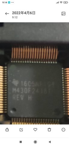
Part Number: MSP430F2418

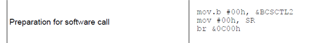
I am using MSP430F2418 on platfrom MSP-TS430PN80 socket. Now I am trying BSL function. The entry as follow:

if((P2IN & BIT0) == 0x00)
{
__disable_interrupt(); // disable interrupts
((void (*)())0x0C00)(); // jump to BSL
}

When I sent a Synchronization 0x80 to BSL receive P2.2 , I could not get the repsonse 0x90 . The BSL transmit line P1.1 was always high that I vefied by scope. I checked the BSL detailed from BSL address and found  somethings 

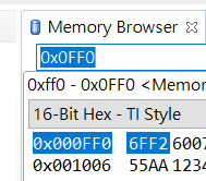
1. the chip id from address 0x0FF0

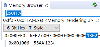
2 the bsl version from address 0xFFA

3. the data from slau319ae

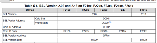
it looks like the ROM information read from MSP430 is F261X device , but my chip is MSP430F2418. I do not know if this is a wrong BSL function in my MSP430 so I could not get the right Sync respinse?

  • Could help to take a picture of the top view of the device? I want to check about the silk information on it.

    By the way when you create a CCS project and choose device MSP430F2418, could you download image into the device by JTAG with any error or warings?

    One comments here that you can try to wait for 300ms that before you send the synchronization 0x80 after you invoke the device by software. I don't know have you try the hardware invoke?

  • It's a photo from my mobile phone shows that it's 2418 device.

    I can develop it by CCS and JTAG normally and it's 2418 targetconfig definitely.

    I waited it 2000ms and no reponse yet. I did not try hardware invocation because the final implementation of the system design by software BSL.

  • Hi 

    For the BSL version that will be fine to use 2.13 to F2418, because the difference between F2418 and F2618 just the DAC and DMA that is not used by BSL.

    I suggest you to use hardware invoke is to verify the BSL image work and the host side operation is work. 

    By the way, do you make any configuration with the pin P1.1 and P2.2 in your application code?

  • hi Gary,

    I tried the hardware invocation and got the response 0x90 correctly.

    I did not config P1.1 and P2.2.

  • hi Gary,

    I did a more test about this phenomenon.

    I wrote the software cdoe that jump to BSL directly after power-up. And checked the response of BSL , no 0x90 still. But at this moment , I did the hardware invocation and checked the respone , the 0x80 returened. Did it mean the software BSL did not work? My code as below:

    int main(void)

    {
    uint16_t ite = 0;
    WDTCTL = WDTPW + WDTHOLD; // Stop watchdog timer
    initClockTo16MHz();
    __bis_SR_register(GIE);
    while (1)
    {
    __disable_interrupt(); // disable interrupts
    for(ite = 0 ; ite < 1000 ; ite++);
    ((void ( * )())0x0C00)(); // jump to BSL
    }

  • Sorry for the late response. 

    Can you try to jump to 0x C02 that used for warm start?

    By the way  the LOCK and LOCKA bits must be cleared by the user application before entering the BSL .

  • Hi Gary,

    Thanks your advice. I  modifed the register as you said and the others as below

    It could go to software BSL. I verified the major cause is SR status! Anyway, I foound another issue happened and maybe created another post to discuss it. 

**Attention** This is a public forum