This thread has been locked.

If you have a related question, please click the "Ask a related question" button in the top right corner. The newly created question will be automatically linked to this question.

MSP430F5132: Are there issues constantly swapping between comparator_B channels? + Code architecture feedback

Part Number: MSP430F5132

Hi Experts!

I would love your input if you expect any issues with my approach. I'm also looking for advice if you think there is a better way to structure the code at a high level.

My questions:

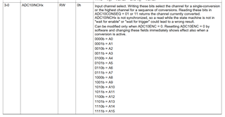
1) Do you expect any issues with constantly switching comparator_B channels?

2) At a high level, can you think of a better code structure?

The goal is to measure two separate, independent signals. One signal I call "AC Fault", the other signal "DC Fault". When AC or DC signal pass a threshold, we must quickly trip a relay. LPM is not a priority, but may be implemented once we have something working.

Our connections would look like 

P1.0: AC Comparator

P1.1: AC ADC

P1.2: DC Comparator

P1.3: DC ADC

An overview of the code:

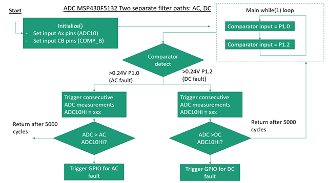
A quick explanation:

a. Switch between comparator input channels constantly. 

b. If comparator interrupt, trigger ADC reading on channel corresponding to comparator. 

c. The comparator tells the MCU if the input signal is an AC or DC fault, then sets the ADC10HI relay trip threshold. 

d. If ADC10HI interrupt is entered, trip a relay

Thank you! 

// My idea for the while loop

    while(1){
        if (faultMode == NO_FAULT) {
            // swap between two comparator channels constantly
            if (index) {
                CBCTL0 |= CBIPSEL_2;            // comp_B input channel CBx <-> IPSEL_x

            } else {
                CBCTL0 |= CBIPSEL_0;            // comp_B input channel CBx <-> IPSEL_x
            }
            // Trigger new ADC read, monitor for fault
        } else {
            ADC10CTL0 &= ADC10ENC;
            ADC10CTL0 |= ADC10ENC + ADC10SC;    
            if (index > FAULT_RESET_DELAY) {
                index = 0;
                faultMode = NO_FAULT;
            }
        }
        index++;

    }

// My idea for the while loop

while(1){
    if (faultMode == NO_FAULT) {
        // swap between two comparator channels constantly
        if (index) {
            CBCTL0 |= CBIPSEL_2;            // comp_B input channel CBx <-> IPSEL_x

        } else {
            CBCTL0 |= CBIPSEL_0;            // comp_B input channel CBx <-> IPSEL_x
        }
        // Trigger new ADC read, monitor for fault
    } else {
        ADC10CTL0 &= ADC10ENC;
        ADC10CTL0 |= ADC10ENC + ADC10SC;    
        if (index > FAULT_RESET_DELAY) {
            index = 0;
            faultMode = NO_FAULT;
        }
    }
    index++;

}

  • Hi Cameron,

    Thanks for putting together such a detailed description of your application.

    Can you share more information about key requirements? What is the required response time? Using the integrated comparator is going to the be fastest. But it also looks like you are going to using the ADC to sample the signal (to confirm the measurement?). I'd expect this to consume the most amount of time in the loop.

    For example, if you are going to perform an ADC measurement anyway why not sample the channels constantly and use the window comparator to trigger an interrupt to trip the relay?

    Again, I don't know what trade-offs will make sense for your application.

    Also, I don't see an issue with rapidly switching between comparator input channels. If you are using power mode=high speed mode, the propagation time is <1us (see 5.43 of the datasheet). I will check with my team to confirm.

    Regards,
    Evan

  • Hi Evan,

    Thank you for the quick response!

    For example, if you are going to perform an ADC measurement anyway why not sample the channels constantly and use the window comparator to trigger an interrupt to trip the relay?

    I like your idea of using a window comparator. We need a response time <20ms. If I use 16 clk cycles for sample and hold (ADC10SHT), an ADC reading would take 28 cycles total, or 1.12us at 25MHz clock speed. For this reason, I think swapping between ADC channels could work

    But it also looks like you are going to using the ADC to sample the signal (to confirm the measurement?). I'd expect this to consume the most amount of time in the loop.

    This is correct. The ADC is used to confirm if we need to trip the relay. 

    New question, if I use the code below, must I include a delay to let the ADC complete the conversion? (the 16 clk sample & hold + 12 clk conversion time)

    I commented where I think the delay is needed.

    // My idea for the while loop using ADC polling 
    
    while(1){
        // swap between two ADC channels constantly
        if (index) {
            init_ADC_DC_mode();              //Set ADC10HI_DC            
            ADC10CTL0 &= ~ADC10ENC;          //trigger a reading
            ADC10CTL0 |= ADC10ENC + ADC10SC;
            // Is a delay needed here?
        } else {
            init_ADC_AC_mode();              //Set ADC10HI_AC
            ADC10CTL0 &= ~ADC10ENC;          //trigger a reading
            ADC10CTL0 |= ADC10ENC + ADC10SC;
            // Is a delay needed here?
        }
        index++;
    }

    thank you!

  • Hi Cameron,

    Thanks for the response. I think achieving a <20ms response time is achievable using this device.

    Please note that the max frequency the ADC can run at is 5Mhz (table 5.29 in the DS). However, I think that should leave plenty of headroom for your application.

    Instead of manually switching between ADC channels in the main loop I would recommend trying to use the "repeat sequence of channels" feature in ADC10A. This features has some limitations: The ADC will start on the channel set in ADCINCHx and proceed sequentially to channel 0. In your case this would limit you to A1 and A0 which could limit your flexibility in board layout. Does this make sense? Section 27.2.7.4 in the user guide has a very detailed state diagram and description of the this process.

    This example shows how to configure the ADC for repeat sequence of channels:

    https://dev.ti.com/tirex/explore/node?node=AFHsHgHjHaWG4XZ9SlF6Kw__IOGqZri__LATEST&search=f5132

    This example shows how to use the window comparator function of the ADC:

    https://dev.ti.com/tirex/explore/node?node=AGQmMIOB7ZvEnJeoWXev5w__IOGqZri__LATEST&search=f5132

    Hopefully that's a good starting point. Let me know if you have any other questions.

    Best,

    Evan

  • Thank you Evan!

    That all makes sense, I am very familiar with those two examples.

    I apologize to bug you with two more questions

    1) Is it ok to change ADC10HI threshold immediately before next conversion? I show this on line 27 and line 30

    2) is it possible to know which ADC channel triggered the interrupt? I show my idea on line 26 and line 29... I have not tested if this works. I'm also curious if there is a better way to do this. This is important because the ADC10HI thresholds will be different for A0 and A1.

    My thoughts in pseudo code:

    // ADC10 interrupt service routine
    #if defined(__TI_COMPILER_VERSION__) || defined(__IAR_SYSTEMS_ICC__)
    #pragma vector=ADC10_VECTOR
    __interrupt void ADC10_ISR(void)
    #elif defined(__GNUC__)
    void __attribute__ ((interrupt(ADC10_VECTOR))) ADC10_ISR (void)
    #else
    #error Compiler not supported!
    #endif
    {
      switch(__even_in_range(ADC10IV,12))
      {
        case  0: break;                         // No interrupt
        case  2: break;                         // conversion result overflow
        case  4: break;                         // conversion time overflow
        case  6:                                // ADC10HI
          ADC10IFG &= ~ADC10HIIFG;              // Clear interrupt flag
          // Trip relay
          break;
    
        case  8: break;                          // ADC10LO
        case 10: break;                          // ADC10IN
        case 12:                                 // ADC10IFG0
            ADC_Result = ADC10MEM0;
            if (ADC10MCTL0 & ADC10INCH_1) { // ADC input = A1
                ADC10HI = A0 trip threshold // Adjust HI threshold to A0 for next conversion
            }
            if (ADC10MCTL0 & ADC10INCH_0) { // ADC input = A0
                ADC10HI = A1 trip threshold // Adjust HI threshold to A1 for next conversion
            }
        break;
        default: break;
      }
    }

    Thank you!

  • 1) Is it ok to change ADC10HI threshold immediately before next conversion? I show this on line 27 and line 30

    Good question. I couldn't find anywhere in the datasheet where this is explicitly forbidden, however I don't think it is advisable. You may end up generating errant interrupts. Example of undesirable behavior: Current ADC value is 0xBB -> you change ADC10HI to 0xAA in preparation for the next sample however the ADC hasn't sampled the next sample yet and see 0xBB in memory and fires an interrupt. To be sure of what the behavior is you'd probably want to do some tests

    2) is it possible to know which ADC channel triggered the interrupt? I show my idea on line 26 and line 29... I have not tested if this works. I'm also curious if there is a better way to do this. This is important because the ADC10HI thresholds will be different for A0 and A1.

    Yes you should be able to read back ADC10INCHx to get the channel last sampled. However, the UG also mentions that you should only read ADC10INCH when you are waiting for a trigger or waiting for an enable. This may limit you a little bit because you won't be able to use ADC10MSC (which automatically re-triggers) instead you will have to retrigger the ADC yourself. The reason is that with MSC enabled you won't ever end up in the wait state where you are allowed to read ADC10INCHx. So perhaps you may want to go back to a more manual approach. Let me think about it and get back to you tomorrow.

    Evan

  • Hi Cameron,

    I thought a little bit more about your application. Since your key requirement (<20ms response time) doesn't stress the system I would suggest avoiding "repeat sequence of channels" with ADC10MSC=1 for now. Even though it will give you the max sampling rate, the code will be more complex.

    The best balance of simplicity and performance would be to configure the device as follows:

    • Use a timer to trigger the ADC. I'm not sure what your target application is but if it is safety related it may be nice to guarantee that you are sampling/responding at a known rate. Using a timer will make sure this is the case.
    • Use the ADC ISR to save off the ADC measurement into global variables
    • In the main loop check the values of the global variables to determine whether to trip.

    Regards,

    Evan

  • Appreciate it Evan!

    This is safety related, so I like the approach of using a timer to sample at a known rate.

**Attention** This is a public forum