This thread has been locked.

If you have a related question, please click the "Ask a related question" button in the top right corner. The newly created question will be automatically linked to this question.

MSP430F5638: SPI works, but can't consistently capture output with SPI data sniffer

Part Number: MSP430F5638

Running the MSP430F5638 on a custom SBC, using CCS 10.4.0.00006, programming P8 UCA1 for SPI, sending data to an IO Ninja SPI data sniffer. When I send a single text string, the sniffer captures most of the transmissions perfectly. If I send the same string continuously, the success capture rate goes down. It the two devices sync, the data sniffer captures it perfectly. So far, can't get the SBC and the data sniffer in sync all the time.

Transmit a single string: run data sniffer, it opens but waits, start program Tx the string, - usually works

Transmit the same string continuously: run the data sniffer, it opens but waits, start the program, and the sniffer captures something or the correct data, start & stop the sniffer repeatedly

MCU UCA1CTL0 SPI settings CPH = CPOL = 11, MSB 1st = 1, 8 bit = 0, high nibble = 1110           Master = 1, 4 pin = 10, synchronous = 1, low nibble = 1101

Sniffer settings: the same, but CPH has to be 0

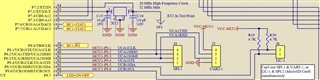
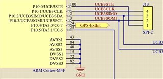
I've added a copy of the P8 serial IO circuit, and the P8 SPI setup, and run function code. The program runs "setup_430_P8_SPI_M_TX( )" either once or continuously.

Any suggestions?

MSP430 P8 SPI Serial IO Functions.c
// setup_430_P8_SPI_1_M_TX() is either run once sending a single fixed string
// or
// run continuously in a loop sending the same string

void setup_430_P8_SPI_1_M_TX(unsigned char *str)
{
    int i=0, length;
    length = strlen(str);

    //SPI_1_M_init_16();        // not working to IO Ninja, don't use
    SPI_1_M_init();           // works Tx to IO Ninja

    // 7654 3210
    // 0001 1110 = 0x1E
    P8SEL |= 0x1E;               // set alternate function for P8.1, P8.2, P8.3, P8.4

    // SPI busy status flag
    // UCAxSTATW->UCBUSY
    //      0 not in Tx or Rx mode
    //      1 busy in either Tx or Rx mode

    // SPI Tx or Rx buffer full flags
    // UCAxIFG->UCTXIFG = bit D1
    //      0 buffer full, can't load with new data
    //      1 buffer empty, ready for new data
    // UCAxIFG->UCRXIFG = bit D0
    //      0 buffer empty, can load new char
    //      1 buffer full, loaded with new char, don't load another char

    // Tx data
    // 7654 3210
    // 0000 0010 = 0x02
    // Tx  while test
    //      true = while loops forever until test fails
    //          0 ANDed with anything = 0, negated = 1
    //      false = while loop ends, code proceeds
    //          both must be true and get negated to 0

    for (i = 0; i < length; i++)
    {
        while(!(UCA1IFG & 2))     // wait for transmit buffer empty
            ;
        UCA1TXBUF = str[i];       // transmit a character
        // was 10, not triggering consistently
        // try 50, same - triggers about 1/2 the time
        // try 500, same
        delayMs(10);
    }
}

void SPI_1_M_init(void)
{
    UCA1CTL1 = 0x01;         // disable UCA1 during configuration

    // 1110 = high nibble
    // clock phase = 1, polarity = 1, MSB first = 1, 8 bit = 0

    // 1101 = low nibble
    // Master = 1, 4-pin SPI = 1, STE low active = 0, synchronous mode = 1

    // 7654 3210
    // 1110 1101 = 0xED
    // CPH = CPOL = 11, MSB 1st = 1, 8 bit = 0      Master = 1, 4 pin STE low & slave enabled low = 10, Synch = 1
    UCA1CTL0 = 0xED;

    // 7654 3210
    // 1000 0001 = 0x81
    // SMCLK = 10, Don't care xxxxx, software reset = 1
    UCA1CTL1 = 0x81;

    // both EUSCI_B3-> and EUSCI_B3_SPI-> work or don't work consistently - they aren't the issue
    // BRW = divisor
    // tested BRW = 2 to 64, must be >= 6 when using X2 @ 24 MHz (432) or XT2 @ 20 MHz (430)
    //EUSCI_B3_SPI->BRW = 1;          // DCO = 3 MHz / 1 = 3 MHz
    //EUSCI_B3->BRW = 8;              // X2 = 24 MHz / 8 = 3 MHz (must be >= 6 to work)
    UCA1BRW = 7;                      // X2 = 20 MHz / 7 = ~3 MHz (must be >= 6 to work)

    UCA1CTL1 &= ~0x01;       // enable UCA1 for use after configuration
}

  • Hi Ted,

    So the SPI output on the MSP430F5638 is consistent and as you expect, but the sniffer itself is reading back inconsistent results?

    Does it look like data is being lost or missed by the sniffer, or that there might be an actual problem with the SPI Output from the MSP? 

    Best Regards,
    Brandon Fisher

  • Hi Brandon,

    Thanks for your reply. Right now the MCU is only sending a fixed string to the sniffer. As long as they synch up correctly, it always shows the correct data. In prior testing I had two MCU's sending data via SPI, with the sniffer in the middle. I need to set that up again as it shows what's happening a little more clearly.

  • Hi Ted,

    That might help clarify. If you have a logic analyzer or scope available, capturing the actual signals may help as well. Just to verify its purely a sniffer configuration problem and not an actual signal problem.

    I'm not sure what the IONinja's output looks like, but from my experience with sniffers its typically just text. Which if your CPH is inverted compared to the MSP probably wont be reliable, since the MSP will be changing the data at the same time the IONinja is trying to capture it. Is the inverted setting for CPH a limitation of the Sniffer? 

    Regards,
    Brandon Fisher

  • Hi Brandon,

    The sniffer is text only, but you can set all of the SPI parameters so it matches the MCU settings. I do have an LA1010 logic analyzer which has worked in the past, but I can't get it to trigger for this current problem. I've tried many different settings. Any suggestions on LA trigger problems? 

  • Hi Ted,

    Make sure your logic and threshold levels are set at a reasonable level. From the LA1010 Software User's Guide it looks like you can configure these for that logic analyzer.

    Other than that there shouldn't be any real trick to capturing your single transaction. You should just be able to set a falling edge trigger on your SCLK or STE pins as described in that user's guide. 

    Best Regards,
    Brandon Fisher

  • When I run this on a MSP432 P10 UCB3 SPI port both the LA1010 & IO Ninja capture everything perfectly whether it's a single string or the same string looping forever. The LA triggers, captures, decodes, and shows everything perfectly: STE goes low, the clock is active while STE is low, MOSI clocks in 1 char - repeats till end of string.

    When I run this on a MSP430 P8 UCA1 SPI port, using the same LA1010 & IO Ninja; the ninja works most of the time in single string mode. But the LA only captures MOSI in asynch mode, and nothing in synch mode. There isn't even a clock or STE pulse, they are always low. This is happening on two different PCB's.

    Other than register name & size differences, the code is the same.

    What would cause the MSP430 P8 SPI clock to not run?

  • Hi Ted,

    The two ports should configure the same, so if that is the only real change you are making is to switch ports, then we may be running into a hardware issue.

    Can you share the portion of your schematic around UCB3? Similar to what you've already shared for UCA1.

    If you have a multimeter handy, can you do a quick continuity test between the pins of J4 and the corresponding device pins? 

    Regards,
    Brandon Fisher

  • Thanks Brandon,

    This is the MSP432 UCB3 circuit - my SPI-1 and SPI-2 pinouts are inconsistent - but they are connected manually with clip leads to either the LA or Ninja. I'll take a look at the solder connections visually with magnifier and a meter.

  • Actually the two SPI outputs are consistent, looked at it a little too quickly earlier. I examined one PCB closely: all 100 pins of the MSP430 look like good solder joints, no bridges; checked continuity between the MCU and J4 - all 4 pins are good. Also toggled P8 bits high and low and they do change.

    The 4 PCB traces from the 432 to SPI-2 header are straight, and about 1" long.

    The PCB traces from the 430 to SPI-1 header (for clock and STE) are circuitous, and about 3-4" long, and go under the MCU - wonder if this is a problem?

  • Ted,

    It's possible, the actual analog waveforms could tell us if if this is something like a timing or noise issue caused by layout.

    Do you have access to an oscilloscope? Seeing the analog waveforms of a SPI transaction may reveal something.

    Best Regards,

    Brandon Fisher

  • Tried two different scopes today, and there is nothing coming out of SPI-1 pins 1,2,3,4, they are all 0, but a DVM and frequency counter gets something???

  • Ted,

    That's interesting, you see no analog waveforms? That wouldn't make sense because you do see activity on your logic analyzer.

    You should be able to set the trigger on your scope to capture at the rising or falling edge of SCLK so you can grab the waveform.

    Best Regards,

    Brandon Fisher

  • Brandon,

    The only device that has worked sometimes is the IO Ninja data sniffer and that is sporadic. The LA1010 sees nothing on all 4 lines like the scopes. I suspect MSP430 P8 is damaged on both PCB's. Thanks for your help. I have to work on another part of this project for now, and have to put this issue on the back burner.

  • I found the problem - seems the MSP430 P8 will not run in SPI 4 pin mode, even if you don't use STE but just use P8.4 as GPIO. In 3 pin mode it works perfectly. The LA1010 triggers, captures, and decodes perfectly either a single string sent once, or the same string sent continuously from P8 tUCA1 o the LA.

**Attention** This is a public forum