


Other Parts Discussed in Thread: ENERGYTRACE
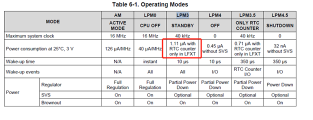
The complete IC model is msp430fr2310irgyr.We have an LED product using this model. In order to test the power consumption of lpm3, we deleted some circuit components, and finally left these components in the figure below. MCU needs periodic sleep wake-up. During 6S of sleep, test and confirm that all P1 and P2 pins output 0V, the total current is about 16.5ua, and the voltage (-v and +v) is 3V. I learned from the manual that the current should be about 1.1ua. I use the demo program provided by Ti to test. Which side of my program is not set correctly? Please give some suggestions.

#include <msp430.h>
void Init_GPIO(void);
unsigned char ucMode = 8;
int main(void)
{
WDTCTL = WDTPW | WDTHOLD; // Stop watchdog timer
// Configure GPIO
Init_GPIO();
// Disable the GPIO power-on default high-impedance mode
// to activate previously configured port settings
PM5CTL0 &= ~LOCKLPM5;
__bis_SR_register(SCG0); // disable FLL
CSCTL3 |= SELREF__REFOCLK; // Set REFO as FLL reference source
CSCTL0 = 0; // clear DCO and MOD registers
CSCTL1 &= ~(DCORSEL_7); // Clear DCO frequency select bits first
CSCTL1 |= DCORSEL_5; // Set DCO = 16MHz
CSCTL2 = FLLD_0 + 487; // DCOCLKDIV = 16MHz
__delay_cycles(3);
__bic_SR_register(SCG0); // enable FLL
while(CSCTL7 & (FLLUNLOCK0 | FLLUNLOCK1)); // FLL locked
CSCTL4 = SELMS__DCOCLKDIV | SELA__REFOCLK; // set default REFO(~32768Hz) as ACLK source, ACLK = 32768Hz
// default DCOCLKDIV as MCLK and SMCLK source
// Configure RTC
RTCMOD = 60-1; // Interrupt and reset happen every 10*1000*(1/10KHz) = ~1S
RTCCTL |= RTCSS__VLOCLK | RTCSR |RTCPS__1000;
RTCCTL |= RTCIE;
while(1)
{
CSCTL5 |= DIVM_1; // MCLK = 0.5* DCOCLKDIV = 8MHz - only for case of temperature changes significantly for LPM3 entry and LPM3 exit
__bis_SR_register(LPM3_bits | GIE); // Enter LPM3, Stop all clocks
__no_operation(); // For debug
}
}
// RTC interrupt service routine
#if defined(__TI_COMPILER_VERSION__) || defined(__IAR_SYSTEMS_ICC__)
#pragma vector=RTC_VECTOR
__interrupt void RTC_ISR(void)
#elif defined(__GNUC__)
void __attribute__ ((interrupt(RTC_VECTOR))) RTC_ISR (void)
#else
#error Compiler not supported!
#endif
{
// Configure the CS
__bic_SR_register(SCG0); // enable FLL
while(CSCTL7 & (FLLUNLOCK0 | FLLUNLOCK1)); // FLL locked
CSCTL5 &= DIVM_1; // MCLK = DCOCLKDIV = 16MHz - only for case of temperature changes significantly for LPM3 entry and LPM3 exit
switch(__even_in_range(RTCIV,RTCIV_RTCIF))
{
case RTCIV_NONE : break; // No interrupt
case RTCIV_RTCIF: __bic_SR_register_on_exit(LPM3_bits); // RTC Overflow
// Exit LPM3 on reti
break;
default: break;
}
}
void Init_GPIO()
{
P1DIR = 0xFF; P2DIR = 0xFF;
P1REN = 0xFF; P2REN = 0xFF;
P1OUT = 0x00; P2OUT = 0x00;
}
