This thread has been locked.
If you have a related question, please click the "Ask a related question" button in the top right corner. The newly created question will be automatically linked to this question.
Please review the MSP430 UART receive. The receive interrupt is triggering too early and data received is incorrect.
PC -> MSP-EXP430FR5994 EUSCIA1UART -> BQ79600-EVM -> custom BQ79616
Breakpoint at:
ReadReg(0, 0x2001, autoaddr_response_frame, 1, 0, FRMWRT_SGL_R);
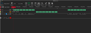
Stepping into this line goes into the UART ISR right away instead of the functions below ReadReg. Only one byte is received, and it is not correct. After this byte, uart ISR does not trigger.
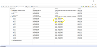
BQ79600 should return 7 bytes in response to the ReadReg 0x2001 command. Address returned should be 0x14 on byte 5.
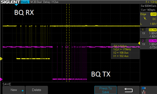
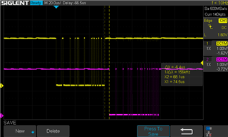
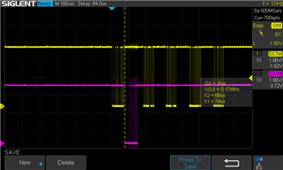
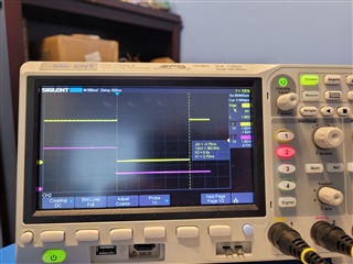
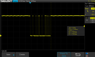
In addition to watching variables/register contents on CCS IDE, I have scope probes on BQ79600 EVM Uart RX and TX.
/* * uartCommands.c * * Created on: Apr 21, 2022 * Author: Priya.Nadathur */ #include <driverlib.h> #include <string.h> #include "bspFuncs.h" #include "mbbConfig.h" #include "uartCommands.h" #include "timer.h" #include "B0_reg.h" #ifdef BQ_UART // CRC16 TABLE // ITU_T polynomial: x^16 + x^15 + x^2 + 1 const uint16_t crc16_table[256] = { 0x0000, 0xC0C1, 0xC181, 0x0140, 0xC301, 0x03C0, 0x0280, 0xC241, 0xC601, 0x06C0, 0x0780, 0xC741, 0x0500, 0xC5C1, 0xC481, 0x0440, 0xCC01, 0x0CC0, 0x0D80, 0xCD41, 0x0F00, 0xCFC1, 0xCE81, 0x0E40, 0x0A00, 0xCAC1, 0xCB81, 0x0B40, 0xC901, 0x09C0, 0x0880, 0xC841, 0xD801, 0x18C0, 0x1980, 0xD941, 0x1B00, 0xDBC1, 0xDA81, 0x1A40, 0x1E00, 0xDEC1, 0xDF81, 0x1F40, 0xDD01, 0x1DC0, 0x1C80, 0xDC41, 0x1400, 0xD4C1, 0xD581, 0x1540, 0xD701, 0x17C0, 0x1680, 0xD641, 0xD201, 0x12C0, 0x1380, 0xD341, 0x1100, 0xD1C1, 0xD081, 0x1040, 0xF001, 0x30C0, 0x3180, 0xF141, 0x3300, 0xF3C1, 0xF281, 0x3240, 0x3600, 0xF6C1, 0xF781, 0x3740, 0xF501, 0x35C0, 0x3480, 0xF441, 0x3C00, 0xFCC1, 0xFD81, 0x3D40, 0xFF01, 0x3FC0, 0x3E80, 0xFE41, 0xFA01, 0x3AC0, 0x3B80, 0xFB41, 0x3900, 0xF9C1, 0xF881, 0x3840, 0x2800, 0xE8C1, 0xE981, 0x2940, 0xEB01, 0x2BC0, 0x2A80, 0xEA41, 0xEE01, 0x2EC0, 0x2F80, 0xEF41, 0x2D00, 0xEDC1, 0xEC81, 0x2C40, 0xE401, 0x24C0, 0x2580, 0xE541, 0x2700, 0xE7C1, 0xE681, 0x2640, 0x2200, 0xE2C1, 0xE381, 0x2340, 0xE101, 0x21C0, 0x2080, 0xE041, 0xA001, 0x60C0, 0x6180, 0xA141, 0x6300, 0xA3C1, 0xA281, 0x6240, 0x6600, 0xA6C1, 0xA781, 0x6740, 0xA501, 0x65C0, 0x6480, 0xA441, 0x6C00, 0xACC1, 0xAD81, 0x6D40, 0xAF01, 0x6FC0, 0x6E80, 0xAE41, 0xAA01, 0x6AC0, 0x6B80, 0xAB41, 0x6900, 0xA9C1, 0xA881, 0x6840, 0x7800, 0xB8C1, 0xB981, 0x7940, 0xBB01, 0x7BC0, 0x7A80, 0xBA41, 0xBE01, 0x7EC0, 0x7F80, 0xBF41, 0x7D00, 0xBDC1, 0xBC81, 0x7C40, 0xB401, 0x74C0, 0x7580, 0xB541, 0x7700, 0xB7C1, 0xB681, 0x7640, 0x7200, 0xB2C1, 0xB381, 0x7340, 0xB101, 0x71C0, 0x7080, 0xB041, 0x5000, 0x90C1, 0x9181, 0x5140, 0x9301, 0x53C0, 0x5280, 0x9241, 0x9601, 0x56C0, 0x5780, 0x9741, 0x5500, 0x95C1, 0x9481, 0x5440, 0x9C01, 0x5CC0, 0x5D80, 0x9D41, 0x5F00, 0x9FC1, 0x9E81, 0x5E40, 0x5A00, 0x9AC1, 0x9B81, 0x5B40, 0x9901, 0x59C0, 0x5880, 0x9841, 0x8801, 0x48C0, 0x4980, 0x8941, 0x4B00, 0x8BC1, 0x8A81, 0x4A40, 0x4E00, 0x8EC1, 0x8F81, 0x4F40, 0x8D01, 0x4DC0, 0x4C80, 0x8C41, 0x4400, 0x84C1, 0x8581, 0x4540, 0x8701, 0x47C0, 0x4680, 0x8641, 0x8201, 0x42C0, 0x4380, 0x8341, 0x4100, 0x81C1, 0x8081, 0x4040 }; BYTE bBuf[8]; uint8_t pFrame[64]; int bRes = 0; BYTE bReturn = 0; BYTE* currCRC; int crc_i = 0; uint16_t wCRC2 = 0xFFFF; int crc16_i = 0; uint8_t uartRxLen; static uint8_t idx; volatile uint8_t rxComplete; BYTE RXData[(1+6)*TOTALBOARDS] = {0}; BYTE response_frame[(8)*TOTALBOARDS]; //store 128 bytes + 6 header bytes for each board // Configure BQ UART @1000000 baud // http://software-dl.ti.com/msp430/msp430_public_sw/mcu/msp430/MSP430BaudRateConverter/index.html void UART_Init(void){ GPIO_setAsPeripheralModuleFunctionInputPin( BQUART_TX_PORT, BQUART_TX_PIN + BQUART_RX_PIN, BQUART_SELECT_FUNCTION ); BQUART_initParam param = {0}; param.clockPrescalar = 4, param.firstModReg = 0, param.secondModReg = 0, param.selectClockSource = BQUART_CLOCKSOURCE; param.parity = BQUART_PARITY; param.msborLsbFirst = BQUART_BITORDER; param.numberofStopBits = BQUART_STOPBIT; param.uartMode = BQUART_MODE; param.overSampling = BQUART_OVERSAMPLING; if(STATUS_FAIL == BQUART_INIT(BQUART, ¶m)) { return; } BQUART_enable(BQUART); BQUART_clearInterrupt(BQUART, BQUART_RX_INT); BQUART_enableInterrupt(BQUART, BQUART_RX_INT); } //FORMAT WRITE DATA, SEND TO //BE COMBINED WITH REST OF FRAME int WriteReg(BYTE bID, uint16_t wAddr, uint64_t dwData, BYTE bLen, BYTE bWriteType){ // device address, register start address, data bytes, data length, write type (single, broadcast, stack) bRes = 0; memset(bBuf,0,sizeof(bBuf)); switch (bLen) { case 1: bBuf[0] = dwData & 0x00000000000000FF; bRes = WriteFrame(bID, wAddr, bBuf, 1, bWriteType); break; case 2: bBuf[0] = (dwData & 0x000000000000FF00) >> 8; bBuf[1] = dwData & 0x00000000000000FF; bRes = WriteFrame(bID, wAddr, bBuf, 2, bWriteType); break; case 3: bBuf[0] = (dwData & 0x0000000000FF0000) >> 16; bBuf[1] = (dwData & 0x000000000000FF00) >> 8; bBuf[2] = dwData & 0x00000000000000FF; bRes = WriteFrame(bID, wAddr, bBuf, 3, bWriteType); break; case 4: bBuf[0] = (dwData & 0x00000000FF000000) >> 24; bBuf[1] = (dwData & 0x0000000000FF0000) >> 16; bBuf[2] = (dwData & 0x000000000000FF00) >> 8; bBuf[3] = dwData & 0x00000000000000FF; bRes = WriteFrame(bID, wAddr, bBuf, 4, bWriteType); break; case 5: bBuf[0] = (dwData & 0x000000FF00000000) >> 32; bBuf[1] = (dwData & 0x00000000FF000000) >> 24; bBuf[2] = (dwData & 0x0000000000FF0000) >> 16; bBuf[3] = (dwData & 0x000000000000FF00) >> 8; bBuf[4] = dwData & 0x00000000000000FF; bRes = WriteFrame(bID, wAddr, bBuf, 5, bWriteType); break; case 6: bBuf[0] = (dwData & 0x0000FF0000000000) >> 40; bBuf[1] = (dwData & 0x000000FF00000000) >> 32; bBuf[2] = (dwData & 0x00000000FF000000) >> 24; bBuf[3] = (dwData & 0x0000000000FF0000) >> 16; bBuf[4] = (dwData & 0x000000000000FF00) >> 8; bBuf[5] = dwData & 0x00000000000000FF; bRes = WriteFrame(bID, wAddr, bBuf, 6, bWriteType); break; case 7: bBuf[0] = (dwData & 0x00FF000000000000) >> 48; bBuf[1] = (dwData & 0x0000FF0000000000) >> 40; bBuf[2] = (dwData & 0x000000FF00000000) >> 32; bBuf[3] = (dwData & 0x00000000FF000000) >> 24; bBuf[4] = (dwData & 0x0000000000FF0000) >> 16; bBuf[5] = (dwData & 0x000000000000FF00) >> 8; bBuf[6] = dwData & 0x00000000000000FF; bRes = WriteFrame(bID, wAddr, bBuf, 7, bWriteType); break; case 8: bBuf[0] = (dwData & 0xFF00000000000000) >> 56; bBuf[1] = (dwData & 0x00FF000000000000) >> 48; bBuf[2] = (dwData & 0x0000FF0000000000) >> 40; bBuf[3] = (dwData & 0x000000FF00000000) >> 32; bBuf[4] = (dwData & 0x00000000FF000000) >> 24; bBuf[5] = (dwData & 0x0000000000FF0000) >> 16; bBuf[6] = (dwData & 0x000000000000FF00) >> 8; bBuf[7] = dwData & 0x00000000000000FF; bRes = WriteFrame(bID, wAddr, bBuf, 8, bWriteType); break; default: break; } return bRes; } //GENERATE COMMAND FRAME int WriteFrame(BYTE bID, uint16_t wAddr, BYTE * pData, BYTE bLen, BYTE bWriteType) { int bPktLen = 0; uint8_t * pBuf = pFrame; uint16_t wCRC; memset(pFrame, 0x7F, sizeof(pFrame)); *pBuf++ = 0x80 | (bWriteType) | ((bWriteType & 0x10) ? bLen - 0x01 : 0x00); //Only include blen if it is a write; Writes are 0x90, 0xB0, 0xD0 if (bWriteType == FRMWRT_SGL_R || bWriteType == FRMWRT_SGL_W) { *pBuf++ = (bID & 0x00FF); } *pBuf++ = (wAddr & 0xFF00) >> 8; *pBuf++ = wAddr & 0x00FF; while (bLen--) *pBuf++ = *pData++; bPktLen = pBuf - pFrame; wCRC = CRC16(pFrame, bPktLen); *pBuf++ = wCRC & 0x00FF; *pBuf++ = (wCRC & 0xFF00) >> 8; bPktLen += 2; //THIS SEEMS to occasionally drop bytes from the frame. Sometimes is not sending the last frame of the CRC. //(Seems to be caused by stack overflow, so take precautions to reduce stack usage in function calls) uartSend(bPktLen, pFrame); return bPktLen; } //GENERATE READ COMMAND FRAME AND THEN WAIT FOR RESPONSE DATA (INTERRUPT MODE FOR SCIRX) int ReadReg(BYTE bID, uint16_t wAddr, BYTE * pData, BYTE bLen, uint32_t dwTimeOut, BYTE bWriteType) { // device address, register start address, byte frame pointer to store data, data length, read type (single, broadcast, stack) int crcChk; bRes = 0; if (bWriteType == FRMWRT_SGL_R) { ReadFrameReq(bID, wAddr, bLen, bWriteType, bLen+6); memset(pData, 0, sizeof(pData)); } else if (bWriteType == FRMWRT_STK_R) { bRes = ReadFrameReq(bID, wAddr, bLen, bWriteType, (bLen + 6) * (TOTALBOARDS - 1)); memset(pData, 0, sizeof(pData)); } else if (bWriteType == FRMWRT_ALL_R) { bRes = ReadFrameReq(bID, wAddr, bLen, bWriteType, (bLen + 6) * TOTALBOARDS); memset(pData, 0, sizeof(pData)); } else { bRes = 0; } // //CHECK IF CRC IS CORRECT for(crc_i=0; crc_i<bRes; crc_i+=(bLen+6)) { if(CRC16(&pData[crc_i], bLen+6)!=0) { // printConsole("\n\rBAD CRC=%04X,i=%d,bLen=%d\n\r",(pData[crc_i+bLen+4]<<8|pData[crc_i+bLen+5]),crc_i,bLen); // PrintFrame(pData, bLen); crcChk = 1; } else crcChk = 0; } /* crc_i = 0; currCRC = pData; for(crc_i=0; crc_i<bRes; crc_i+=(bLen+6)) { printConsole("%x",&currCRC); if(CRC16(currCRC, bLen+6)!=0) { printConsole("BAD CRC=%04X,byte=%d\n\r",(currCRC[bLen+4]<<8|currCRC[bLen+5]),crc_i); PrintFrame(pData, bLen); } *currCRC+=(bLen+6); } */ return crcChk; } int ReadFrameReq(BYTE bID, uint16_t wAddr, BYTE bByteToReturn, BYTE bWriteType, BYTE rxLen) { bReturn = bByteToReturn - 1; uartRxLen = rxLen; idx = 0; rxComplete = 0; if (bReturn > 127) return 0; return WriteFrame(bID, wAddr, &bReturn, 1, bWriteType); } uint16_t CRC16(BYTE *pBuf, int nLen) { wCRC2 = 0xFFFF; //printConsole("CRCOUT = \t"); for (crc16_i = 0; crc16_i < nLen; crc16_i++) { //printConsole("%02x ",*pBuf); wCRC2 ^= (*pBuf++) & 0x00FF; wCRC2 = crc16_table[wCRC2 & 0x00FF] ^ (wCRC2 >> 8); } //printConsole("\n\r"); return wCRC2; } void uartSend(int length, uint8_t * data){ uint8_t i; for (i = 0; i < length; i++){ while (!(UCA1IFG & UCTXIFG)); BQUART_TXBUF = data[i]; } } void uartReceive(BYTE * data, BYTE length){ } //****************************************************************************** // SPI_B1 Interrupt ************************************************************ //****************************************************************************** #pragma vector=BQUART_VECTOR /******************************************************************************* USCI_A1_ISR ****************************************************************** ******************************************************************************* * Function: A1 Interrupt Routine ********************************************************************************/ __interrupt void BQUART_ISR(void) { switch(__even_in_range(BQUART_IV, USCI_UART_UCTXCPTIFG)) { case USCI_NONE: break; case USCI_UART_UCRXIFG: BQUART_IFG &= ~UCRXIFG; RXData[idx] = EUSCI_A_UART_receiveData(BQUART); idx++; if (idx == uartRxLen){ rxComplete = 1; } break; case USCI_UART_UCTXIFG: break; case USCI_UART_UCSTTIFG: break; case USCI_UART_UCTXCPTIFG: break; default: break; } } #endif
Hi Priya,
Could you reduce the amount of provided code to a minimum that still demonstrates the issue?\
Could you also show the main code around where you set your breakpoint?
Thank you
I uploaded a scaled down project with only the BQ initialization sequence (wake up, auto address) With this project, the UART Rx ISR is not triggering at all. I do see one BQ response on the scope. The code related to all uart commands (with the BQ wrapper) is also in this post. Maybe the larger project had a different trigger for UART receive, I don't know what. I can see that the OE error flag is set from the register contents. There is some byte in the Uart Rx and Tx buffers.
The breakpoint is set at line 122 of BQUartInitFuncs.c in my upload today (BQInitUartJun142022.zip). Please let me know if you have all the needed information.
Hi Priya,
I am currently reading through your code to find the issue. As I am reading, I wanted to point out that I do not see where you are enabling the UART RX interrupt. I see that you enable global interrupts, but I can not find your enable for UART RX interrupts. Please verify that you do perform this step, as it is critical to enter the ISR you've written for receives.
I see in your recent reply that when you hit your breakpoint that you've set, the UCOE flag of the UCA1MCTLW register is set, along with the UCRXERR flag. These two flags will be set whenever there is a character loaded into the UCA1RXBUF before the previous character has been read. More information on these flags can be found in section 30 of the MSP430FR58xx, MSP430FR59xx, and MSP430FR6xx Family User's Guide (linked below), and specific information about the flags can be found in Table 30-1.
MSP430FR58xx, MSP430FR59xx, and MSP430FR6xx Family User's Guide (Rev. P) (ti.com)
Please verify the above information as soon as possible as I continue to look for potential errors in your project.
void UART_Init(void){ GPIO_setAsPeripheralModuleFunctionInputPin( BQUART_TX_PORT, BQUART_TX_PIN + BQUART_RX_PIN, BQUART_SELECT_FUNCTION ); BQUART_initParam param = {0}; param.clockPrescalar = 4, param.firstModReg = 0, param.secondModReg = 0, param.selectClockSource = BQUART_CLOCKSOURCE; param.parity = BQUART_PARITY; param.msborLsbFirst = BQUART_BITORDER; param.numberofStopBits = BQUART_STOPBIT; param.uartMode = BQUART_MODE; param.overSampling = BQUART_OVERSAMPLING; if(STATUS_FAIL == BQUART_INIT(BQUART, ¶m)) { return; } BQUART_enable(BQUART); BQUART_clearInterrupt(BQUART, BQUART_RX_INT); BQUART_enableInterrupt(BQUART, BQUART_RX_INT); }
I enable the UART Rx interrupt in the UART_Init function. I call the UART_Init before the auto address. Do I need to do this in more places?
I did clean up my workspace and import the CCS project. The BQInit roject has the same behavior as the larger BQ project. The UART ISR triggers once receiving an incorrect byte and then not anymore.
FYI-- I uploaded the BQInit project with recent minor edits. I kept the same project name. Please get a latest download when looking at this project, thanks.
Looking at your code it appears that you expect no data until you are ready for it. But it seems that isn't happening.
What I see is: 1) Initialize UART and enable receive interrupt.
2) Set idx =0;
3) Send command.
4) Expect data.
The problem is that your code will process received data before the command is sent. It doesn't even check to make sure the index doesn't run past the end of the array. Sure it sets a flag but it doesn't disable RXIE and will keep storing data and incrementing idx. Writing over whatever lies beyond.
Even if no data is expected you must code defensively.
I made the following changes to the uart send and ISR. There is no change in the receive data.
void uartSend(int length, uint8_t * data){ uint8_t i; idx = 0; rxComplete = 0; BQUART_IE |= UCRXIE; for (i = 0; i < length; i++){ while (!(UCA1IFG & UCTXIFG)); BQUART_TXBUF = data[i]; } } #pragma vector=BQUART_VECTOR /******************************************************************************* USCI_A1_ISR ****************************************************************** ******************************************************************************* * Function: A1 Interrupt Routine ********************************************************************************/ __interrupt void BQUART_ISR(void) { switch(__even_in_range(BQUART_IV, USCI_UART_UCTXCPTIFG)) { case USCI_NONE: break; case USCI_UART_UCRXIFG: BQUART_IFG &= ~UCRXIFG; RXData[idx] = BQUART_RXBUF; if (idx < uartRxLen) idx++; if (idx == uartRxLen){ rxComplete = 1; BQUART_IE &= ~UCRXIE; } break; case USCI_UART_UCTXIFG: break; case USCI_UART_UCSTTIFG: break; case USCI_UART_UCTXCPTIFG: break; default: break; } }
If I put a breakpoint at the very end of uartSend, I can see BQ receive activity on the scope, though I don't exactly know what bytes are coming in. The timing of the ISR is not capturing this receive data. I need more pointers on what to do here.
You mentioned breakpoints. What is your "normal" test case? Do you let it run with no breakpoints?
I ask since, if you set a breakpoint at the end of uartSend, you will (for that test run) lose all of the (BQ-side) Tx data since the MSP-side UART (SMCLK) is stopped while you're at the breakpoint.
(Perhaps this is obvious, but someone has to ask.)
Unsolicited: Don't clear RXIFG explicitly in the ISR -- it has already been cleared by reading the IV, and it will be cleared (again) by reading RXBUF. The symptom would be the loss of one out of each pair of bytes, which is not your symptom (yet).
I removed clearing RXIFG from the uart ISR. The only breakpoint in the test run is at
//OPTIONAL: read register address 0x2001 and verify that the value is 0x14
ReadReg(0, 0x2001, autoaddr_response_frame, 1, 0, FRMWRT_SGL_R);
This helps capture the BQ receive better. There is one BQ receive activity seen and then none after.
Hi Priya,
For the BQ79600, can you capture a Salae/logic analyzer log and provide? This will help us debug from the BQ79600 Rx side.
We are interested in the following....
Thanks,
Tom
As I read this scope trace, the MCU is sending (yellow line) repeatedly, but only gets a response (purple line) to the first request.
3) The configuration looks fine. (Priya, I'm assuming you're using the same #-defines as over in the other thread (?).)
[Edit: 3+) I don't know how the clocks are set, but the scope trace (eyeball accuracy) indicates 1usec bit time -> 1Mbps.]
Priya,
After reviewing further, I have two notes for you:
1) This may be obvious, but to be sure, in your UART_Init function, when the BQUART_Init function executes, if it fails, the function returns and your main code executes the same as if the BQUART_Init function passed. You've said the RX ISR executes once, so it seems that this function is passing, and executing the interrupt enables, but it might be wise to add an assert or some other check to ensure that this isn't failing and then your device tries communicating over UART anyways. Aside from this, I haven't found anything that is incorrect in your UART_Init function.
2) In your configure_pins_BQUart function, I see that you put both Pins 2.5 and 2.6 in output mode. This may be an issue, as typically the approach to utilize your GPIO pins for their UART functionality does not involve changing the PxOUT bits associated with those pins. Pins 2.5 and 2.6 are UCA1TXD and UCA1RXD respectively, when utilizing their secondary module function. To put these pins into these secondary module functions, you must set bits 5 and 6 of P6SEL1, and clear bits 5 and 6 of P6SEL0. For reference on this, you may want to visit TI's resource explorer, and follow the path MSP430Ware -> Devices -> MSP430FR5xx_6xx -> MSP430FR5994 -> Peripheral Examples -> Register Level, and then select either MSP430FR599x_euscia0_uart_01.c, or MSP430FR599x_euscia0_uart_02.c.
Let us know if any improvements occur when making these adjustments to the P2.5 and P2.5 settings.
I hesitate to disagree with Dylan, but:
1) EUSCI_A_UART_init (as of 3.80.07.00) never fails. I suppose it's still a good idea to crash or something if it does, but it's not relevant to this thread.
2) To get SECONDARY function, you set the P2SEL1 bits and clear the P2SEL0 bits. [Ref data sheet (SLASE54C) Table 6-25]. GPIO_setAsPeripheralModuleFunctionInputPin does this correctly. As Table 6-25 note (2) points out, the GPIO direction setting is irrelevant with the EUSCI.
In short: You don't need to change anything here.
Attached are the BQ Wakeup Pulse and green light; Uart Read frame request following ReadReg(0, 0x2001, autoaddr_response_frame, 1, 0, FRMWRT_SGL_R);
I have incorporated feedback from all responses here about the uart isr. I assume it has been set up correctly. I have added the BQ transmit transaction scope picture.
I will gather the logic analyzer data next.
Id,Time[ns],0:UART: RX/TX 0,10000800.00000000000000000000,80 1,10010800.00000000000000000000,00 2,10020800.00000000000000000000,20 3,10030800.00000000000000000000,01 4,10040800.00000000000000000000,00 5,10050800.00000000000000000000,25 6,10060800.00000000000000000000,84 7,10143800.00000000000000000000,B0 8,10153800.00000000000000000000,03 9,10163800.00000000000000000000,31 10,10173800.00000000000000000000,FF 11,10183800.00000000000000000000,83 12,10193800.00000000000000000000,34 13,10271000.00000000000000000000,B0 14,10281000.00000000000000000000,03 15,10291000.00000000000000000000,32 16,10301000.00000000000000000000,FF 17,10311000.00000000000000000000,83 18,10321000.00000000000000000000,C4 19,10402800.00000000000000000000,90 20,10412800.00000000000000000000,00 21,10422800.00000000000000000000,20 22,10432800.00000000000000000000,30 23,10442800.00000000000000000000,22 24,10452800.00000000000000000000,71 25,10462800.00000000000000000000,CE 26,10540000.00000000000000000000,B0 27,10550000.00000000000000000000,00 28,10560000.00000000000000000000,17 29,10570000.00000000000000000000,01 30,10580000.00000000000000000000,E8 31,10590000.00000000000000000000,D4
I am able to gather the BQ TX data and all uart transmit messages are correct. However the BQ TX is not showing up consistently anymore on the scope and I am not able to capture it using the logic analyzer.
I got the trigger settings correct now. The BQ Tx is actually the correct response. For some reason it is not reaching the MSP430 uart. I am able to save only the uart tx to a text file. I took a screenshot of the uart rx.
Attached are the BQ Wakeup Pulse and green light; Uart Read frame request following ReadReg(0, 0x2001, autoaddr_response_frame, 1, 0, FRMWRT_SGL_R);
I have incorporated feedback from all responses here about the uart isr. I assume it has been set up correctly. I have added the BQ transmit transaction scope picture.
I will gather the logic analyzer data next.
Id,Time[ns],0:UART: RX/TX 0,10000800.00000000000000000000,80 1,10010800.00000000000000000000,00 2,10020800.00000000000000000000,20 3,10030800.00000000000000000000,01 4,10040800.00000000000000000000,00 5,10050800.00000000000000000000,25 6,10060800.00000000000000000000,84 7,10143800.00000000000000000000,B0 8,10153800.00000000000000000000,03 9,10163800.00000000000000000000,31 10,10173800.00000000000000000000,FF 11,10183800.00000000000000000000,83 12,10193800.00000000000000000000,34 13,10271000.00000000000000000000,B0 14,10281000.00000000000000000000,03 15,10291000.00000000000000000000,32 16,10301000.00000000000000000000,FF 17,10311000.00000000000000000000,83 18,10321000.00000000000000000000,C4 19,10402800.00000000000000000000,90 20,10412800.00000000000000000000,00 21,10422800.00000000000000000000,20 22,10432800.00000000000000000000,30 23,10442800.00000000000000000000,22 24,10452800.00000000000000000000,71 25,10462800.00000000000000000000,CE 26,10540000.00000000000000000000,B0 27,10550000.00000000000000000000,00 28,10560000.00000000000000000000,17 29,10570000.00000000000000000000,01 30,10580000.00000000000000000000,E8 31,10590000.00000000000000000000,D4
I am able to gather the BQ TX data and all uart transmit messages are correct. However the BQ TX is not showing up consistently anymore on the scope and I am not able to capture it using the logic analyzer.
I got the trigger settings correct now. The BQ Tx is actually the correct response. For some reason it is not reaching the MSP430 uart. I am able to save only the uart tx to a text file. I took a screenshot of the uart rx. I note that to keep getting a BQ response byte, I need to
Once I stopped putting a breakpoint in the UART ISR to track every incoming byte, the contents of RXData match the BQ response seen on the logic analyzer. I find I get consistent receive triggers when I use the default value for TX_HOLDOFF BQ register. Seems like the issue is resolved. If I run into difficulties when moving forward with development, I will start a new thread. Many thanks.
**Attention** This is a public forum