This thread has been locked.

If you have a related question, please click the "Ask a related question" button in the top right corner. The newly created question will be automatically linked to this question.

MSP430FR5043: MSP430FR5043: I2C communication with BQ25700A IC , MSP430FR5043 not giving ACK

Part Number: MSP430FR5043
Other Parts Discussed in Thread: BQ25700A,

Hi

I'm trying to interface MSP430FR5043 with BQ25700A , but while testing , it was found that MSP430FR5043 is giving ACK for data received from BQ25700A . Refer waveform below.

Slave address 0x12H with R/W bit as zero is given from MSP430. Here slave BQ25700A gives ACK.

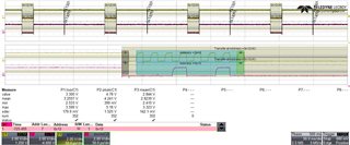
Then Command 0x34H is given from MSP430. Here slave BQ25700A gives ACK.

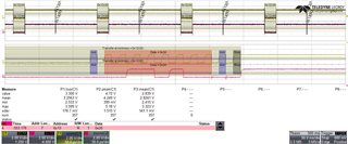
Slave address 0x13H is given with R/W bit as one from MSP430, then slave BQ25700A gives data 0x20 but MSP430 is not giving ACK for data received and thus communication fails.

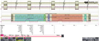
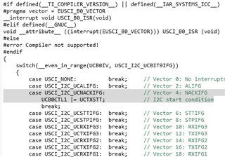
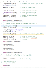
Here we suspect that MSP set the ACK bit before BQ25700A slave and by the time clock comes it is treated as NACK.

Suggest a fix for this issue.

Regards

Bivin

  • Hi Bivin,

    For 0x13H, this is a I2C read command, correct?

    Have you use this example code to test I2C read function?

    https://dev.ti.com/tirex/explore/node?node=AM2CqGohFh.JSojcZJH6mA__IOGqZri__LATEST

    Thanks!

    Best Regards

    Johnson

  • Hi Johnson

    Are you suggesting to use below highlighted portion in case of NACK, please confirm.

    Can you let me know why MSP430 is not pulling SDA line low which is set by BQ25700A slave

    Is there a way to set ACK bit separately.

  • The MSP430 I2C hardware will normally handle the ACK just fine. Which makes me suspect something is wrong with your code. But I can't tell since you haven't shown it.

  • It appears that your code is issuing a Stop after (during) receiving the first byte. In this case, the I2C unit generates a NACK to the current Rx byte [Ref User Guide (SLAU367P) Sec 32.3.5.2.2].

    What does your code look like?

  • Hi

    Please find the code below.

    Please comment on the same.

  • My first guess is that i2c_addn_config_b0() is trying to update UCB0TBCNT without resetting UCB0 (toggling UCSWRST), so it's still =1 during the read phase.

    What does that function do exactly? 

    Unsolicited: You really should wait for UCRXIFG0 to go high again before reading UCB0RXBUF the second time. I suspect this is (will be) working-by-accident due to your write to the serial port.

  • Vast portions of the code are missing. (Please use the insert code button to post code, an image capture is a horrible way to do this.) Initialization and the interrupt service routine.  Plus of course that code to set the byte count for an automatic stop. (Note: that register must only be changed when UCSWRST=1.)

    If this code was used to generate the captures then you left off the initial part of the data.

    The receive code is a nightmare. You enable the receive interrupt and then poll RXIFG. You can't do both. The ISR will field the receive interrupt and the main routine will never ever see a set RXIFG so it will just wait forever without reading RXBUF. Plus of course that bit about reading RXBUF a second time without waiting for a second RXIFG.

    It also appears as though you are issuing a stop after transmitting one byte. The usual way to handle this is with a repeated start. Not a full stop.

**Attention** This is a public forum