- Ask a related questionWhat is a related question?A related question is a question created from another question. When the related question is created, it will be automatically linked to the original question.
This thread has been locked.
If you have a related question, please click the "Ask a related question" button in the top right corner. The newly created question will be automatically linked to this question.


Hi,
Thanks for sharing this question. We will look into this and get back to you soon.
Regards,
Evan
Hi Kenton,
Something doesn't seem right here. Seeing such a large drift would equate to a substantial change in temperature.
You didn't say which mode you are using so I will assume self cap.
Can you tell me a little about the product? Is it a portable device for mounted, like a thermostat on a wall?
Looking at the Captivate Tech Guide, design chapter, section on temperature drift, and based on your device being a GEN1 device, the drift should be -2.6cnt/C (self cap), or -.2cnt/C (mutual cap).
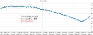
Looking at your top graph, the count changes from 500 to 470. So based on my assumption the 30count change would = 11.5C change. Is it possible where this device is located it experienced that much change in temperature?
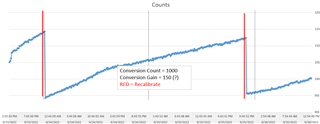
Next, the points at where the re-calibration appears to occur doesn't seem correct either. A recalibration occurs if, since the last calibration, the LTA has drifted by +/- 12.5%. Looking at your middle graph where the first recalibration appears to happen at ~478 counts, then the next one at ~ 485 makes no sense. The LTA would have to go as high as 540 before a recalibration should occur.
There are two other reasons why a recalibration will occur; one is if the MSP is told to recalibrate, or if there is a negative touch detected. I see no evidence of a negative touch, so that would rule that out. Do you have a host MCU that talks to the MSP and sends it commands?
The third graph appears to be a different sensor (a proximity sensor) because over time it's counts goes up, compared to the other two graphs.
And for driven shield, there is no code required for this. There is a section in the Tech Guide that briefly talks about this and shows some tests that were performed when the shield electrode is driven by a very fast, OPA354 amplifier.
Many thanks for the response, Dennis!
Here is some additional information, per your response:
Thanks again!
Hi Kenton,
Regarding the driven shield, yes, using another pin that is same measurement cycle in most cases will work. It may not work as effectively if the capacitance of the shield is much greater than the electrode (sensor). In other words, the pin driving the larger capacitance of the shield may take longer to fully charge compared to the pin that is driving the electrode's capacitance.
Ok, now that we confirmed you are using self capacitance and that this is all happening at room temp, the first two graphs' downward direction (lower counts) would indicate the capacitance that the sensor is measuring is increasing, similar to when you touch the sensor. The third graph, with increasing counts, tells me the sensor is measuring decreasing capacitance. But what is interesting is for self cap the DOI (direction of interest) is down. This means when the sensor is touched, the count value should go lower than the LTA. In this case the drift is causing the count to go higher than the LTA, which would be considered a "negative touch" if the count reaches the negative touch threshold.
Can you describe what exactly you are using as the sensor?
Thanks, Dennis!
We can't share full details of our design here (for business reasons). Would it be possible to have a private conversation with TI, and then post general findings here for the community?
Thanks again!
Sure thing, Evan! I sent Dennis a friend-request, and am hoping to connect if he is willing.
Appreciate the help again!
**Attention** This is a public forum