This thread has been locked.

If you have a related question, please click the "Ask a related question" button in the top right corner. The newly created question will be automatically linked to this question.

MSP430F247: MSP low-power microcontroller forum

Part Number: MSP430F247
Other Parts Discussed in Thread: BQ76940,

Hi,

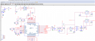
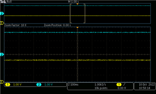
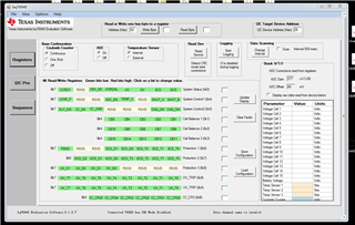
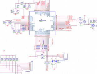
I am using 247 to communicate to an I2C device, bq76940.  The 247 is unable to talk to the I2C device. I have risen the issue to the bq support group for quite while.  This process is resulted  in  believing the problem is in mastor side of the system. Our design is to use msp430f247 MCU as mastor to communicate to bq76940 as a slave device. The firmware handling the I2C part of code is taking from ti recommanded demo code. Here below is my questions,
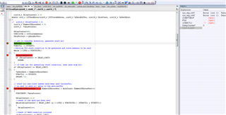
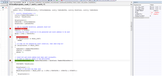
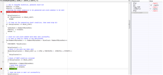
the debug snapshot

The actual code is as follow,

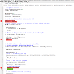
static int8_t I2CSendBytes(uint8_t I2CSlaveAddress, uint8_t *pDataBuffer, uint16_t ByteCount, uint16_t *pSentByte)
{
  uint16_t DelayCounter = 0;
  uint16_t NumberOfBytesSent = 0;
  uint8_t *DataPointer;

  UCB0I2CSA = I2CSlaveAddress;
  DataPointer = pDataBuffer;

  // set to transfer direction, generate start bit
  UCB0CTL1 |= UCTR;
  UCB0CTL1 |= UCTXSTT;
  //waiting for start condition to be generated and slave address to be sent
  while (!(IFG2 & UCB0TXIFG))
  {
    DelayCounter ++;
    if (DelayCounter >= DELAY_LIMIT)
      break;
  }

  // if time out for generating start condition, then send stop bit
  if (DelayCounter >= DELAY_LIMIT)
  {
    *pSentByte = NumberOfBytesSent;
    UCB0CTL1 |= UCTXSTP;
    return -1;
  }


  // start bit and slave addree have been sent successful,
  // so next to send all datas in the data-buffer
  for(NumberOfBytesSent = 0; NumberOfBytesSent < ByteCount; NumberOfBytesSent++)
  {
    UCB0TXBUF= *DataPointer;

    DelayCounter = 0;
    //check if the byte has been sent
    while(DelayCounter < DELAY_LIMIT && (!(IFG2 & UCB0TXIFG) || (UCB0CTL1 & UCTXSTT)))
    {
      DelayCounter++;
    }
    //check if NACK condition occurred
    if(DelayCounter >= DELAY_LIMIT)
    {
      *pSentByte = NumberOfBytesSent;
      //send stop condition
      UCB0CTL1 |= UCTXSTP;
      return -1;
    }

    // here one byte is sent out successfully
    DataPointer++;
  }

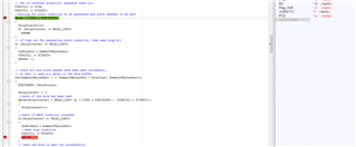
  // all datas are sent, clear TX flag, send stop bit
  IFG2 &= ~UCB0TXIFG;
  UCB0CTL1 |= UCTXSTP;
  DelayCounter = 0;
  while(DelayCounter < DELAY_LIMIT && ((UCB0CTL1 & UCTXSTP)))
  {
    DelayCounter++;
  }
  *pSentByte = NumberOfBytesSent;
  //check if NACK condition occurred
  if (DelayCounter >= DELAY_LIMIT)
  {
    UCB0CTL1 |= UCSWRST;
    return -1;
  }
  else
  return 0;
}

My question is when execution is stopped at break point, why are the UCTXSTP bit and the UCTXSTT bit  already set?

thanks

  • 1. What is your optimization level?

    2. Do you meet any problem when you use this code?

    3. Can you use an oscilloscope to catch the wave to see whether it generate a stop bit?

  • I don't see where you set the alternate function(s) for P3.1-2 to UCB0SDA/SCL, something like:

    > P3SEL |= (BIT1 | BIT2);   // P3.1-2 as UCB0SDA/SCL per data sheet (SLAS547I) Table 23

  • Hi Bruce,

    Here is the set up of I2C stuff

    void I2C_Initialise()
    {
      UCB0CTL1 |= UCSSEL_2+UCSWRST; // enable SW reset, use SMCLK as USCI clock source
      //UCB0CTL1 |= UCSSEL_1+UCSWRST; // enable SW reset, use ACLK as USCI clock source
      UCB0CTL0 = UCMST + UCMODE_3 + UCSYNC; // set to I2C master mode
      UCB0BR0 = 20; // 92.16KHz @0.9216MHz of Aclk, make sure SCLK does not exceed 100KHz
      UCB0BR1 = 0;
      UCB0I2CIE = 0; // disable nack, stop condition detected, start condition detected, arbitration-lost interrupts
      IE2 &= ~(UCB0TXIE + UCB0RXIE); // disable Tx&Rx interrupts
      UCB0CTL1 &= ~UCSWRST; // release from reset state
      bqI2CError = FALSE; // clear i2c fault error flag
      bqI2CStatusReadError = NO_SIGNIFICANCE;
    }

    static void gpioInit(void)
    {
      P1DIR |= 0xdf;
      P1OUT |= 0;

      P2SEL |= 0x20;
      P2DIR |= 0xf7;
      P2OUT |= 0;

      P3SEL |= 0x36;
      P3DIR |= 0xd9;
      P3OUT = 0;

      P4DIR |= 0xff;
      P4OUT = 0;

      P5SEL |= 0x0f;
      P5DIR |= 0xfa;
      P5OUT = (SPI_CS_BIT+RED_LED_BIT+GRN_LED_BIT);

      P6SEL |= 0xff;
      P6DIR |= 0x00;
    }

    static void DCO_init(void)
    {
      //Select max DCO tap
      DCOCTL = DCO0+DCO1+DCO2;

      //turn on OSC
      _BIC_SR(OSCOFF);

      //RSEL0+RSEL1+RSEL2,Select range 7
      //XTS, HF mode
      //divider for ACLK is 2 , FRG:921600!!!!!!!!!!!!
      BCSCTL1 = (XTS+XT2OFF+DIVA_1+RSEL0+RSEL1+RSEL2);

      //MCLK source is DCOCLK
      //Divider for MCLK 1
      //SMCLK source from LFXT1CLK
      //Divider for SMCLK: 2, FRQ: 921600
      //DCO resistor select External resistor
      BCSCTL2=DCOR+DIVS0+SELS;

      //when XTS=1, LFXT1S_1 1-3MHZ crystal
      BCSCTL3 = (LFXT1S_1 + XCAP_0);

      do{
        IFG1 &= ~OFIFG;
        for(unsigned int i = 255; i> 0; i--);
      } while((IFG1 & OFIFG));
    }

    regard

  • Hi Eason,

    Here is my optimization set up

    Here is wave form captured,

    You can see no signals present either on clock (yellow), or data (blue).

    So I did the debug process as i posted in the original form,

    I found the UCTXSTT and UCTXSTP bits are set to 1 from start to end of  I2CSendBytes routine call, it sounds not right.

    I have no problem to compiling the code.

    Best regard.

    Thanks

  • I expect the reason both STT and STP are set is that the Previous operation failed (timed out). Since UCTR=0, that operation was presumably a Read. Do you have a corresponding I2CReadBytes()?

    Also: Over in the other thread you said "I have tested the BQ76940 on my board by using TI evaluation software, the BQ76940 is working well.". Which TI evaluation software were you working with?

  • Hi Bruce,

    Here is read I2C bytes function

    int8_t I2CReadBytes(uint8_t I2CSlaveAddress, uint8_t *pDataBuffer, uint16_t ExpectedByteNumber, uint16_t *pNumberOfReceivedBytes)
    {
      uint16_t DelayCounter = 0;
      uint8_t *DataPointer;
      uint16_t *NumberOfReceivedBytesPointer;

      NumberOfReceivedBytesPointer = pNumberOfReceivedBytes;
      *NumberOfReceivedBytesPointer = 0;
      DataPointer = pDataBuffer;
      UCB0I2CSA = I2CSlaveAddress;

      //data in receive direction, generate start conditon

      UCB0CTL1 &= ~(UCTR);
      UCB0CTL1 |= UCTXSTT;
      while((UCB0CTL1 & UCTXSTT))
      {
        DelayCounter ++;
        if (DelayCounter >= DELAY_LIMIT)
        break;
      }


      if (DelayCounter >= DELAY_LIMIT || UCB0STAT & UCNACKIFG) //check if NACK condition occured
        return -1;

      for (*NumberOfReceivedBytesPointer = 0; *NumberOfReceivedBytesPointer < ExpectedByteNumber; (*NumberOfReceivedBytesPointer)++)
      {
        if(*NumberOfReceivedBytesPointer + 1 == ExpectedByteNumber)
        UCB0CTL1 |= UCTXSTP;
        DelayCounter = 0;
        while(DelayCounter < DELAY_LIMIT && !(IFG2 & UCB0RXIFG))
        {
          DelayCounter++;
        }

        if (DelayCounter == DELAY_LIMIT)
        {
          UCB0CTL1 |= UCSWRST; //if I2C overtime condition occurrd, reset I2C engine
          return -1;
        }
        *DataPointer = UCB0RXBUF;
        DataPointer++;
      }

      DelayCounter = 0;
      while(DelayCounter < DELAY_LIMIT && (UCB0CTL1 & UCTXSTP))
      {
        DelayCounter++;
      }

      if (DelayCounter >= DELAY_LIMIT)
      {
        UCB0CTL1 |= UCSWRST;
        return -1;
      }
      return 0;
    }

    int8_t I2CReadRegisterByteWithCRC(uint8_t I2CSlaveAddress, uint8_t Register, uint8_t *Data)
    {
      uint8_t TargetRegister = Register;
      uint16_t SentByte = 0;
      uint8_t ReadData[2];
      uint16_t ReadDataCount = 0;
      uint8_t CRCInput[2];
      uint8_t CRC = 0;
      int8_t ReadStatus = 0;
      int8_t WriteStatus = 0;

      WriteStatus = I2CSendBytes(I2CSlaveAddress, &TargetRegister, 1, &SentByte);

      ReadStatus = I2CReadBytes(I2CSlaveAddress, ReadData, 2, &ReadDataCount);

      if (ReadStatus != 0 || WriteStatus != 0)
      {
        return -1;
      }

      CRCInput[0] = (I2CSlaveAddress << 1) + 1;
      CRCInput[1] = ReadData[0];

      CRC = CRC8(CRCInput, 2, CRC_KEY);

      if (CRC != ReadData[1])
        return -1;

      *Data = ReadData[0];
      return 0;
    }

    You can see from above, no matter you do write register or read register operation,  the I2CSendBytes(I2CSlaveAddress, &TargetRegister, 1, &SentByte) function is always called first. So i disagree that the STT bit and the STP bit are set by previous read operation.

    Here is the bq769x0 evaluation software i used

    best regard

    thanks

  • The hardware won't set TXSTT or TXSTP on its own, so something in your program must have. Since the call (debugger screen) you showed stopped before either was set, it must have been the previous call.

    The trick with a timed-out request is that you never quite know what state the bus was left in. So if one operation failed, the next might Start/time-out/Stop and continue executing, leaving TXSTT and TXSTP set. Thus it's useful to catch the first failure (maybe the first transaction).

    Also, the EUSCI (and thus I suspect the USCI) I2C unit has trouble if a Start (TXSTT) is requested while a Stop (TXSTP) is still pending; when I've seen this in the EUSCI, the bus is left stuck, with (as I recall) SCL low, but the behavior might be slightly different with the USCI.

    It looks as though you're making I2C requests (via BqGetRegisterByte and BqSetRegisterByte) from an ISR. Are you quite certain that this could never happen while another transaction is running?

  • Hi Bruce,

    Here is the first transaction capured ,

    Just as you described the two bits are set by program its self, i have traced the UCB0CTL1 register value.

    Then question arise, as the menu said,

    1> when the start bit is set, the i2c module will generate star condition and transmit slave address byte, and the start bit will cleared automatically after START condition and address information is transmitted.

    2>.when the stop bit is set, the i2c module will generate stop condition and UCTXSTP is automatically cleared after STOP is generated.

    Why are the two bits  not cleared by I2c module atomatically? Becaues of no ack from slave?  Hardware issue ?

    The failed point at the break point of green colour, the primary reason is UCB0TXIFG not set.

    I do see the IFG2 register volue change between the to break points

    Any suggestion?

    best regard,

  • Hi Bruce,

    I am quite sure i did not use any interrupt related to I2C.

  • Hi Bruce,

    I do have an isr,

    //port1 interrupt service routine
    #pragma vector=PORT1_VECTOR
    __interrupt void isr_port_1(void)
    {
      if (P1IFG & BIT5)
      {
        // read SYS_STAT byte
        bqI2CError = NO_SIGNIFICANCE;
        bqStatus.StatusByte = BqGetRegisterByte(SYS_STAT);
        bqI2CStatusReadError = bqI2CError;
        BqSetRegisterByte(SYS_STAT, STAT_CC_READY);
        P1IFG &= ~BIT5; // clear interrupt flag
      }
    }

    I disable the isr when doing the debug.

  • If TXSTT or TXSTP don't auto-clear, that suggests something wrong with the bus which prevents the Start or Stop setup. (The I2C unit has a bus monitor which checks to see that its bus manipulations are effective.) That, along with your always-high scope trace, was why I first suspected that you had forgotten the P3SEL bits.

    "Something wrong" covers a number of cases, the usual suspects are (1) missing pullups (2) physically disconnected (3) SDA and/or SCL held low.

    When you used the TI GUI, how did you tap into your board? I don't see any jumpers in the schematic fragments you've posted.

    What are DELAY_LIMIT and I2CSlaveAddress set to?

  • Hi Bruce,

    the DELAY_LIMIT is 0xffff, the slave address is 8.

  • It seems you even don't send out the I2C address successfully. I would you try this example code, to see whether you can catch some wave on the bus.

    msp430x24x_uscib0_i2c_01.c
    /* --COPYRIGHT--,BSD_EX
     * Copyright (c) 2012, Texas Instruments Incorporated
     * All rights reserved.
     *
     * Redistribution and use in source and binary forms, with or without
     * modification, are permitted provided that the following conditions
     * are met:
     *
     * *  Redistributions of source code must retain the above copyright
     *    notice, this list of conditions and the following disclaimer.
     *
     * *  Redistributions in binary form must reproduce the above copyright
     *    notice, this list of conditions and the following disclaimer in the
     *    documentation and/or other materials provided with the distribution.
     *
     * *  Neither the name of Texas Instruments Incorporated nor the names of
     *    its contributors may be used to endorse or promote products derived
     *    from this software without specific prior written permission.
     *
     * THIS SOFTWARE IS PROVIDED BY THE COPYRIGHT HOLDERS AND CONTRIBUTORS "AS IS"
     * AND ANY EXPRESS OR IMPLIED WARRANTIES, INCLUDING, BUT NOT LIMITED TO,
     * THE IMPLIED WARRANTIES OF MERCHANTABILITY AND FITNESS FOR A PARTICULAR
     * PURPOSE ARE DISCLAIMED. IN NO EVENT SHALL THE COPYRIGHT OWNER OR
     * CONTRIBUTORS BE LIABLE FOR ANY DIRECT, INDIRECT, INCIDENTAL, SPECIAL,
     * EXEMPLARY, OR CONSEQUENTIAL DAMAGES (INCLUDING, BUT NOT LIMITED TO,
     * PROCUREMENT OF SUBSTITUTE GOODS OR SERVICES; LOSS OF USE, DATA, OR PROFITS;
     * OR BUSINESS INTERRUPTION) HOWEVER CAUSED AND ON ANY THEORY OF LIABILITY,
     * WHETHER IN CONTRACT, STRICT LIABILITY, OR TORT (INCLUDING NEGLIGENCE OR
     * OTHERWISE) ARISING IN ANY WAY OUT OF THE USE OF THIS SOFTWARE,
     * EVEN IF ADVISED OF THE POSSIBILITY OF SUCH DAMAGE.
     *
     *******************************************************************************
     * 
     *                       MSP430 CODE EXAMPLE DISCLAIMER
     *
     * MSP430 code examples are self-contained low-level programs that typically
     * demonstrate a single peripheral function or device feature in a highly
     * concise manner. For this the code may rely on the device's power-on default
     * register values and settings such as the clock configuration and care must
     * be taken when combining code from several examples to avoid potential side
     * effects. Also see www.ti.com/grace for a GUI- and www.ti.com/msp430ware
     * for an API functional library-approach to peripheral configuration.
     *
     * --/COPYRIGHT--*/
    //******************************************************************************
    //  MSP430x24x Demo - USCI_B0 I2C Master to TMP100, Set P1.0 if Temp > 28C
    //
    //  Description: I2C interface to TMP100 temperature sensor in 9-bit mode.
    //  Timer_A CCR0 interrupt is used to wake up and read the two bytes of
    //  the TMP100 temperature register every 62ms. If the temperature is greater
    //  than 28C, P1.0 is set, else reset. CPU is operated in LPM0. I2C speed
    //  is ~100kHz.
    //  ACLK = n/a, MCLK = SMCLK = TACLK = BRCLK = default DCO = ~1.045Mhz
    //
    //         /|\           /|\ /|\
    //          |   TMP100   10k 10k     MSP430F249
    //          |   -------   |   |   -------------------
    //          +--|Vcc SDA|<-|---+->|P3.1/UCB0SDA    XIN|-
    //          |  |       |  |      |                   |
    //          +--|A1,A0  |  |      |               XOUT|-
    //             |       |  |      |                   |
    //          +--|Vss SCL|<-+------|P3.2/UCB0SCL   P1.0|---> LED
    //         \|/  -------          |                   |
    //
    //  B. Nisarga
    //  Texas Instruments Inc.
    //  September 2007
    //  Built with CCE Version: 3.2.0 and IAR Embedded Workbench Version: 3.42A
    //******************************************************************************
    #include <msp430.h>
    
    unsigned int RxByteCtr;
    unsigned int RxWord;
    
    int main(void)
    {
      WDTCTL = WDTPW + WDTHOLD;                 // Stop WDT
      P1OUT  = 0;
      P1DIR |= 0x01;                            // P1.0 output
      P3SEL |= 0x06;                            // Assign I2C pins to USCI_B0
      UCB0CTL1 |= UCSWRST;                      // Enable SW reset
      UCB0CTL0 = UCMST + UCMODE_3 + UCSYNC;     // I2C Master, synchronous mode
      UCB0CTL1 = UCSSEL_2 + UCSWRST;            // Use SMCLK, keep SW reset
      UCB0BR0 = 12;                             // fSCL = SMCLK/12 = ~100kHz
      UCB0BR1 = 0;
      UCB0I2CSA = 0x4E;                         // Set slave address
      UCB0CTL1 &= ~UCSWRST;                     // Clear SW reset, resume operation
      IE2 |= UCB0RXIE;                          // Enable RX interrupt
      TACTL = TASSEL_2 + MC_2;                  // SMCLK, contmode
    
      while (1)
      {
        RxByteCtr = 2;                          // Load RX byte counter
        UCB0CTL1 |= UCTXSTT;                    // I2C start condition
        __bis_SR_register(CPUOFF + GIE);        // Enter LPM0, enable interrupts
                                                // Remain in LPM0 until all data
                                                // is RX'd
    
        if (RxWord < 0x1d00)                    // >28C?
          P1OUT &= ~0x01;                       // No, P1.0 = 0
        else
          P1OUT |= 0x01;                        // Yes, P1.0 = 1
    
        __disable_interrupt();
        TACCTL0 |= CCIE;                        // TACCR0 interrupt enabled
        __bis_SR_register(CPUOFF + GIE);        // Enter LPM0, enable interrupts
                                                // Remain in LPM0 until TACCR0
                                                // interrupt occurs
        TACCTL0 &= ~CCIE;                       // TACCR0 interrupt disabled
      }
    }
    
    #if defined(__TI_COMPILER_VERSION__) || defined(__IAR_SYSTEMS_ICC__)
    #pragma vector = TIMERA0_VECTOR
    __interrupt void TA0_ISR(void)
    #elif defined(__GNUC__)
    void __attribute__ ((interrupt(TIMERA0_VECTOR))) TA0_ISR (void)
    #else
    #error Compiler not supported!
    #endif
    {
      __bic_SR_register_on_exit(CPUOFF);        // Exit LPM0
    }
    
    // The USCIAB0TX_ISR is structured such that it can be used to receive any
    // 2+ number of bytes by pre-loading RxByteCtr with the byte count.
    #if defined(__TI_COMPILER_VERSION__) || defined(__IAR_SYSTEMS_ICC__)
    #pragma vector = USCIAB0TX_VECTOR
    __interrupt void USCIAB0TX_ISR(void)
    #elif defined(__GNUC__)
    void __attribute__ ((interrupt(USCIAB0TX_VECTOR))) USCIAB0TX_ISR (void)
    #else
    #error Compiler not supported!
    #endif
    {
      RxByteCtr--;                              // Decrement RX byte counter
    
      if (RxByteCtr)
      {
        RxWord = (unsigned int)UCB0RXBUF << 8;  // Get received byte
        if (RxByteCtr == 1)                     // Only one byte left?
          UCB0CTL1 |= UCTXSTP;                  // Generate I2C stop condition
      }
      else
      {
        RxWord |= UCB0RXBUF;                    // Get final received byte,
                                                // Combine MSB and LSB
        __bic_SR_register_on_exit(CPUOFF);      // Exit LPM0
      }
    }
    
    
    msp430x24x_uscib0_i2c_04.c
    /* --COPYRIGHT--,BSD_EX
     * Copyright (c) 2012, Texas Instruments Incorporated
     * All rights reserved.
     *
     * Redistribution and use in source and binary forms, with or without
     * modification, are permitted provided that the following conditions
     * are met:
     *
     * *  Redistributions of source code must retain the above copyright
     *    notice, this list of conditions and the following disclaimer.
     *
     * *  Redistributions in binary form must reproduce the above copyright
     *    notice, this list of conditions and the following disclaimer in the
     *    documentation and/or other materials provided with the distribution.
     *
     * *  Neither the name of Texas Instruments Incorporated nor the names of
     *    its contributors may be used to endorse or promote products derived
     *    from this software without specific prior written permission.
     *
     * THIS SOFTWARE IS PROVIDED BY THE COPYRIGHT HOLDERS AND CONTRIBUTORS "AS IS"
     * AND ANY EXPRESS OR IMPLIED WARRANTIES, INCLUDING, BUT NOT LIMITED TO,
     * THE IMPLIED WARRANTIES OF MERCHANTABILITY AND FITNESS FOR A PARTICULAR
     * PURPOSE ARE DISCLAIMED. IN NO EVENT SHALL THE COPYRIGHT OWNER OR
     * CONTRIBUTORS BE LIABLE FOR ANY DIRECT, INDIRECT, INCIDENTAL, SPECIAL,
     * EXEMPLARY, OR CONSEQUENTIAL DAMAGES (INCLUDING, BUT NOT LIMITED TO,
     * PROCUREMENT OF SUBSTITUTE GOODS OR SERVICES; LOSS OF USE, DATA, OR PROFITS;
     * OR BUSINESS INTERRUPTION) HOWEVER CAUSED AND ON ANY THEORY OF LIABILITY,
     * WHETHER IN CONTRACT, STRICT LIABILITY, OR TORT (INCLUDING NEGLIGENCE OR
     * OTHERWISE) ARISING IN ANY WAY OUT OF THE USE OF THIS SOFTWARE,
     * EVEN IF ADVISED OF THE POSSIBILITY OF SUCH DAMAGE.
     *
     *******************************************************************************
     * 
     *                       MSP430 CODE EXAMPLE DISCLAIMER
     *
     * MSP430 code examples are self-contained low-level programs that typically
     * demonstrate a single peripheral function or device feature in a highly
     * concise manner. For this the code may rely on the device's power-on default
     * register values and settings such as the clock configuration and care must
     * be taken when combining code from several examples to avoid potential side
     * effects. Also see www.ti.com/grace for a GUI- and www.ti.com/msp430ware
     * for an API functional library-approach to peripheral configuration.
     *
     * --/COPYRIGHT--*/
    //******************************************************************************
    //  MSP430x24x Demo - USCI_B0 I2C Master RX single bytes from MSP430 Slave
    //
    //  Description: This demo connects two MSP430's via the I2C bus. The master
    //  reads from the slave. This is the master code. The data from the slave
    //  transmitter begins at 0 and increments with each transfer. The received
    //  data is in R5 and is checked for validity. If the received data is
    //  incorrect, the CPU is trapped and the P1.0 LED will stay on. The USCI_B0
    //  RX interrupt is used to know when new data has been received.
    //  ACLK = n/a, MCLK = SMCLK = BRCLK = default DCO = ~1.045Mhz
    //
    // ***to be used with "msp430x24x_uscib0_i2c_05.c" ***
    //
    //                                /|\  /|\
    //               MSP430F249       10k  10k     MSP430F249
    //                   slave         |    |        master
    //             -----------------   |    |  -----------------
    //           -|XIN  P3.1/UCB0SDA|<-|---+->|P3.1/UCB0SDA  XIN|-
    //            |                 |  |      |                 | 32kHz
    //           -|XOUT             |  |      |             XOUT|-
    //            |     P3.2/UCB0SCL|<-+----->|P3.2/UCB0SCL     |
    //            |                 |         |             P1.0|--> LED
    //
    //  B. Nisarga
    //  Texas Instruments Inc.
    //  September 2007
    //  Built with CCE Version: 3.2.0 and IAR Embedded Workbench Version: 3.42A
    //******************************************************************************
    #include <msp430.h>
    
    unsigned char RXData;
    unsigned char RXCompare;
    
    int main(void)
    {
      WDTCTL = WDTPW + WDTHOLD;                 // Stop WDT
      P1OUT &= ~0x01;                           // P1.0 = 0
      P1DIR |= 0x01;                            // P1.0 output
      P3SEL |= 0x06;                            // Assign I2C pins to USCI_B0
      UCB0CTL1 |= UCSWRST;                      // Enable SW reset
      UCB0CTL0 = UCMST + UCMODE_3 + UCSYNC;     // I2C Master, synchronous mode
      UCB0CTL1 = UCSSEL_2 + UCSWRST;            // Use SMCLK, keep SW reset
      UCB0BR0 = 12;                             // fSCL = SMCLK/12 = ~100kHz
      UCB0BR1 = 0;
      UCB0I2CSA = 0x048;                        // Slave Address is 048h
      UCB0CTL1 &= ~UCSWRST;                     // Clear SW reset, resume operation
      IE2 |= UCB0RXIE;                          // Enable RX interrupt
      RXCompare = 0x0;                            // Used to check incoming data
    
      while (1)
      {
        while (UCB0CTL1 & UCTXSTP);             // Ensure stop condition got sent
        UCB0CTL1 |= UCTXSTT;                    // I2C start condition
        while (UCB0CTL1 & UCTXSTT);             // Start condition sent?
        UCB0CTL1 |= UCTXSTP;                    // I2C stop condition
        __bis_SR_register(CPUOFF + GIE);        // Enter LPM0 w/ interrupts
    
        if (RXData != RXCompare)                // Trap CPU if wrong
        {
          P1OUT |= 0x01;                        // P1.0 = 1
          while (1);                            // Trap CPU
        }
    
        RXCompare++;                            // Increment correct RX value
      }
    }
    
    // USCI_B0 Data ISR
    #if defined(__TI_COMPILER_VERSION__) || defined(__IAR_SYSTEMS_ICC__)
    #pragma vector = USCIAB0TX_VECTOR
    __interrupt void USCIAB0TX_ISR(void)
    #elif defined(__GNUC__)
    void __attribute__ ((interrupt(USCIAB0TX_VECTOR))) USCIAB0TX_ISR (void)
    #else
    #error Compiler not supported!
    #endif
    {
      RXData = UCB0RXBUF;                       // Get RX data
      __bic_SR_register_on_exit(CPUOFF);        // Exit LPM0
    }
    

  • I just noticed that your scope trace says "1.00kS/s". Is this correct? At 100kHz clock, a byte takes about (8+1)*0.01ms, so you could fit an entire transaction into 1ms.

    Is there a way to turn up the resolution on your scope? Alternatively (perhaps simpler?) slow the bus way down by setting e.g. BR0=100.

    The TXSTT/TXSTP behavior still suggests that there's something wrong with the bus, but maybe higher "magnification" will tell us something.

  • Hi Bruce, Eason,

    I have a good news. Thay are talking now. The problem turns out to be in clock setup.  Originally the SMCLK  source is  from external crystal, then SMCLK is selected as I2C clock. This does not work for I2C function. I make SMCLK source from DCO, then I still select SMCLK as I2C clock, this is working.

    Finally i use ACLK as I2C clock, it is working too.  I have still one issue before this thread can be closed.

    In my firmware there is an interrupt routine to serve the bq76940 trigger signal. In side the routine i make two calls to I2C manipulation.

    //port1 interrupt service routine
    #pragma vector=PORT1_VECTOR
    __interrupt void isr_port_1(void)
    {
      //DIS_P1INT();
      if (P1IFG & BIT5)
      {
        // read SYS_STAT byte
        bqStatus.StatusByte = BqGetRegisterByte(SYS_STAT);
        bqI2CStatusReadError = bqI2CError;
        // clear CC reading bit
        BqSetRegisterByte(SYS_STAT, STAT_FLAGS|STAT_CC_READY);
      }
      P1IFG &= ~BIT5; // clear interrupt flag
    }

    When it is starting to run for a short time, the execution runs away eventually.

    Can you explain me the reason behind the sence if possible.

    Thanks Bruce,Eason again for a great help.

    Best regard!

  • What do you mean with "the execution runs away eventually?" Do you mean the PC jump to unwanted place?

  • Can you help check after running which code, the program run away? Maybe the access to the array is over range.

  • Hi Eason,

    //port1 interrupt service routine
    #pragma vector=PORT1_VECTOR
    __interrupt void isr_port_1(void)
    {
      //DIS_P1INT();
      if (P1IFG & BIT5)
      {
        // read SYS_STAT byte
        bqStatus.StatusByte = BqGetRegisterByte(SYS_STAT);
        bqI2CStatusReadError = bqI2CError;
        // clear CC reading bit
        BqSetRegisterByte(SYS_STAT, STAT_FLAGS|STAT_CC_READY);
      }
      P1IFG &= ~BIT5; // clear interrupt flag

    }

    I believe the execution run away in side the interrupt routine above beacuse I remove the code to read\write of I2C to some where outside of interrupt service routine the execution never dies.

    regard.

  • Can you test this in debug mode and set a breakpoint at the beginning of the IRQ?

    I want to check whether this problem happens on the IRQ jump or the code in the IRQ.

  • The two main hazards in running the I2C (or any peripheral really) in an ISR:

    1) If your I2C code uses interrupts, it will presumably set GIE=1 somewhere. If done from an ISR, it's very easy to end up with (a) ISR recursion leading to (b) stack overflow leading to (c) "branch to nowhere". I don't see your code doing this, but the symptom matches your description.

    2) If the interrupt happens while main() is in the middle of an I2C operation, the ISR will come in and mess with the registers for the operation in progress. This may cause a failure in its operation, or simply leave an inconsistent state for the operation main() was in the middle of. The usual symptom here is an infinite loop (in the ISR or in main()), but this seems the more probable failure given the code you've shown.

    You might consider disabling P1IE.5 at the beginning of each I2C operation, then re-enabling it at the end (cheap insurance). This will keep the ALERT pending until it's safe to reset CC_READY.

  • Hi Bruce, Eason,

    I am still using my old way to handle alert signal from bq76940, like ,

    //port1 interrupt service routine
    #pragma vector=PORT1_VECTOR
    __interrupt void isr_port_1(void)
    {
      if (P1IFG & BIT5)
      {
        // read SYS_STAT byte
        bqStatus.StatusByte = BqGetRegisterByte(SYS_STAT);
        bqI2CStatusReadError = bqI2CError;
        // clear CC reading bit
       BqSetRegisterByte(SYS_STAT, STAT_CC_READY);
      }
      P1IFG &= ~BIT5; // clear interrupt flag
    }

    But i do put code to disable port 1 i/o interrupt in the start of  int8_t I2CSendBytes(uint8_t I2CSlaveAddress, uint8_t *pDataBuffer, uint16_t ByteCount, uint16_t *pSentByte),

    and int8_t I2CReadBytes(uint8_t I2CSlaveAddress, uint8_t *pDataBuffer, uint16_t ExpectedByteNumber, uint16_t *pNumberOfReceivedBytes)  I2C routine,

    and enable port 1 i/o interrupt at end of these I2C routines call.

    It is working fine now. 

    This way, the system can reduce power consumption a lot because the supply current will increase by about 25 uA while the alert signal is active. The longer time period alert remains high, the more power  it is consuming.

    Sorry Eason I can't reproduce the run away problem. Don't know why.

    Best regard

**Attention** This is a public forum