Part Number: MSP430F5324
Other Parts Discussed in Thread: CC1101, MSP430F5328
MSP430F5324IRGCR High Failure Rate
Failure Details
Mode 1:
Successfully downloaded firmware, but LED D1 is OFF.
Failure rate: 23.75% (1900 out of 8000)
Mode 2:
Successfully downloaded firmware, LED D1 is blinking when powered by MSP-EXP430G2 (3.5V)
When assembled to HF sensor (3V, 150mA), the board resets.
Failure rate: 12.5% (1000 out of 8000)
Mode 1 Failure Analysis
Successfully downloaded firmware, but LED D1 is OFF.
a) Current Consumption
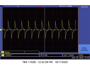
Good unit:
By applying 3VDC to the DUT, the expected minimum operation current is at least 7.5mA.
Green LED is blinking.
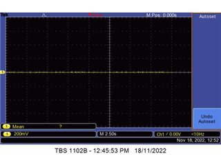
Bad unit:
By applying 3VDC to the DUT, the bad unit current is only 2mA.
Green LED always off.
b) ABA Swap Analysis
We performed ABA swap on MCU between good unit and bad.
Good unit became failed after swapped MCU from bad unit.
It has the same failure symptom.
Bad unit became passed after swapped MCU from good unit.
c) Replace new MCU and Retest
We replaced new MCU on 12 units bad unit.
It turns out 9 units passed and 3 units remain failed after replaced new MCU.
d) Rework failure rate: 25% (3 out of 12)
The failure symptom for these 3 units is the same (LED OFF).
We performed ABA swap analysis on these 3 failed units by swapping MCU to a known good unit.
Good unit become failed after swap MCU from bad unit.
Bad unit become passed after swap MCU from good unit.
This shows that the raw part is defective.
Conclusion
With above findings, we can conclude that the MCU is defective. It is the failure root cause.
With 23.75% failure rate, it is suggested that the raw part is unreliable for production usage.
Mode 2 Failure Analysis
Successfully downloaded firmware, LED D1 is blinking.
But when assembled with Sensor Board, it cannot defect motion.
a) Current Consumption
Good unit:
By applying 3VDC to the DUT, the expected minimum operation current is at least 7.5mA.
Green LED is blinking.
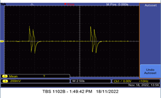
Bad unit:
By applying 3VDC to the DUT, the bad unit current is 8.8mA slightly higher than the expected operation current. Green LED is blinking twice and off, blinking twice and off, suspect MCU is being reset.
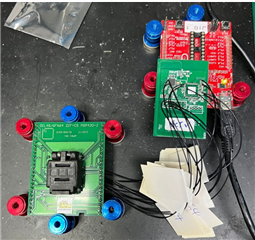
We found bad unit RF Network card required higher voltage (>3.5V) or higher current limit (>400mA) in order to function properly.
RF Network card power reset/not able to sync up when connected to HF Sensor board.
HF Sensor board is providing 3V@150mA to RF Network card.
b) ABA Swap Analysis
We performed ABA swap on MCU between good unit and bad.
Good unit became failed after swapped MCU from bad unit.
It has the same failure symptom.
Bad unit became passed after swapped MCU from good unit.
c) Replace new MCU and Retest
We replaced a new MCU on bad unit.
Unit passed after replaced a new MCU.
Conclusion
With above findings, we can conclude that the MCU is defective. It is the failure root cause.
With 12.5% failure rate, it is suggested that the raw part is unreliable for production usage.