This thread has been locked.

If you have a related question, please click the "Ask a related question" button in the top right corner. The newly created question will be automatically linked to this question.

MSP430F5324: PWM generator of TimerB in MSP430F5324

Part Number: MSP430F5324

Hi e2e,


There is a problem about Timer output of TimerB in MSP430F5324.

The first pulse is not what we expected if change the frequency. It is bigger than expected value, and the pulse is longer than expected;


Here is a example case.


Function requirement:

            Output PWM definition. (Changing step is 25ms.)


Timer and mode selection:

            CCR0 is working for frequency.

CCR2 is working for duty cycle.


Code:

Init function:

void enable_timerB_tone() {

            TB0CCR0 = 0;

            TB0CCR2 = 0;

            TB0CCTL2 = CLLD_1 | OUTMOD_6;

            TB0CTL = TBSSEL__SMCLK + MC__UP + ID__2 + TBCLR;

        }


Each 25ms to change parameters to change the frequency:

void set_parameters_timerB(uint16_t period, uint16_t pulse_width_counter) {

            TB0CCR0 = period;

            TB0CCTL0 = CLLD_3;

            TB0CCR2 = pulse_width_counter;

        }


Result:

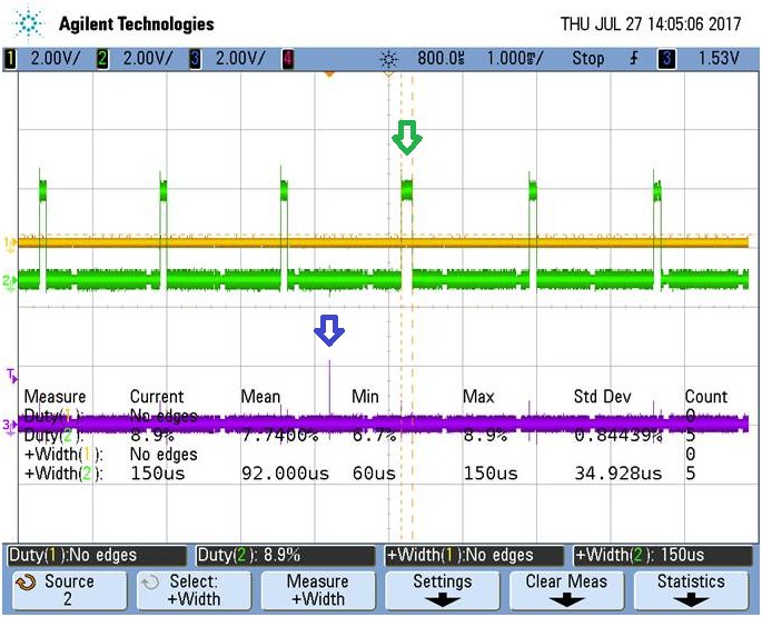
Check output with OSC:

The Purple line mark the parameter changing time(GPIO toggle for debugging, it indicates the value change in MCU).

The Green line is the output of CCR2.

The Purple arrow is the time to call “set_parameters_timerB()” function (it is finished also).

The Green arrow is the problem pulse.


(Before changing the pulse is 90us, after problem is 100us. Both side are correct as parameters.)

(From the rising edge of problem pulse to the next rising edge of pulse, the period is also bigger than expected value.)


 do you have any suggestion in this issue?

thanks in advance.

LEON


  • Hi Leon,

    I'm checking this issue and will reply you when I get an idea.
  • Hi Leon,

    did you check if following note from users guide is considered in your project:

  • Hi Leon,

    Did you check the suggestion by Dietmar?
  • Hi Jetim,

    I am not sure it is correct or not as my understand. It means need to stop timer B before operation registers (nearly all of registers). Current, our requirement needs to update frequece and duty cycle continuously.

    And, if need to do stop whatever. How to understand "CCLD" register and "TBCLGRP" register, and how to use them.

    Thank you! Thanks for your reply.
  • Hi Jetim,

    I am not sure it is correct or not about my understand of Dietmar's comments. "Need to do stop Timer B, before operate registers (nearly all of them)."

    Current, our requerment is a solution to update frequecy and duty cycle continuously.

    And, if need to stop timer B whatever. How to understand the meaning of "CLLD" and "TBCLGRP" register.

    Thank you! Thanks for your reply!
  • Hi Jetim,

    I am not sure it is correct or not about my understand of Dietmar's comments. "Need to do stop Timer B, before operate registers (nearly all of them)."

    Current, our requirement is a solution to update frequency and duty cycle continuously.

    And, if need to stop timer B whatever. How to understand the meaning of "CLLD" and "TBCLGRP" register.

    Thank you! Thanks for your reply!
  • Hi Leon,

    if I understand your code correct, you use the SMCLK which is sourced by DCO which means you're running you clocks beteween Timer and CPU syncronously right?

    In your init funciton you use CLLD = 01b means TBxCLn loads when TBxR counts to 0.

    When you update the frequency (TB0CCR0) and duty cycle values (TB0CCR2) you change the CLLD settings to 11b TBxCLn loads when TBxR counts to TBxCLn

    So can you tell me the values you write to TB0CCR0 and TB0CCR2 are these the same values?
    It the scope it looks like because after the 100us pulse you can see 90us pules again right?

    So the idea is update the frequency and pulse width after the next period right (period after the green arrow in your picutre)?
    This is because the old value should still be in the compare latches right?

    Does it help to change the order of the update function to following:

    void set_parameters_timerB(uint16_t period, uint16_t pulse_width_counter) {

                TB0CCR0 = period;

                TB0CCR2 = pulse_width_counter;

                TB0CCTL0 = CLLD_3;

            }

  • Hi Leon,
    any update on the requested information above or did you resolved the situation already?
  • Hi Dietmar,

    Currently there is no feedback from customer, i will have a check with them, thanks for your notation.

    LEON

**Attention** This is a public forum