This thread has been locked.

If you have a related question, please click the "Ask a related question" button in the top right corner. The newly created question will be automatically linked to this question.

MSP430F2274-EP: BSL Programming Pins

Genius 14569 points
Part Number: MSP430F2274-EP
Other Parts Discussed in Thread: MSP-FET

Hi Experts,

Seeking your assistance on this query:

I am having a hard time fitting a JTAG connection on my board. I am interested in the BSL programming.

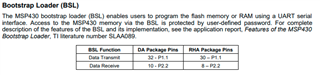
I need to verify that pins 25 and 26 are used for BSL programming - MSP430F2274MDATEP.

25: P3.4/UCA0TXD/UCA0SIMO
26: P3.5/UCA0RXD/UCA0SOMI

Thank you.

Regards,
Archie A.

  • No JTAG/Spy-Bi-Wire connection on the target design means the MCU cannot be debugged in-circuit with an MSP-FET or equivalent. According to the datasheet, this device supports Spy-Bi-Wire, which is a two-wire debugger/programming interface. As long as that's understood...

    Page 10 of the datasheet, SLAS614D, shows the BSL's UART pins are actually pins 32 (P1.1) for BSL TX and 10 (P2.2) for BSL RX on the DA package.

  • Hello,

    Please see the BSL section of the device datasheet for BSL pinout information. For this device, they are pins P1.1 and P2.2. Also keep in mind you still need access to the TEST and RST pins in order to invoke BSL, unless you do SW invoke. This device does not include BSL invocation on blank device feature.

    Please also keep in mind the programming/debug hardships brought up by Seth as BSL does not have any debug capabilities. Only flashing the device. 

  • Jace, thanks for chiming in and adding that the BSL requires TEST and RST (the two Spy-Bi-Wire pins) for invocation anyways...my response was definitely insufficient.

**Attention** This is a public forum