This thread has been locked.

If you have a related question, please click the "Ask a related question" button in the top right corner. The newly created question will be automatically linked to this question.

MSP430FR6877: LFXT fault, no oscillation

Part Number: MSP430FR6877

I have designed a custom board with msp430fr6877.

Start debug with the example code for  RTC.

The code stuck with LFXT fault flag.

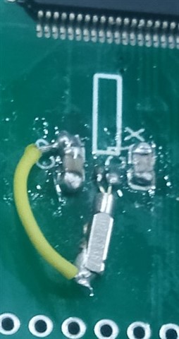
Later I checked with scope at LFXTIN and LFXTOUT but there was nothing, no oscillation atall. Only some hundred milivolt dc voltage.

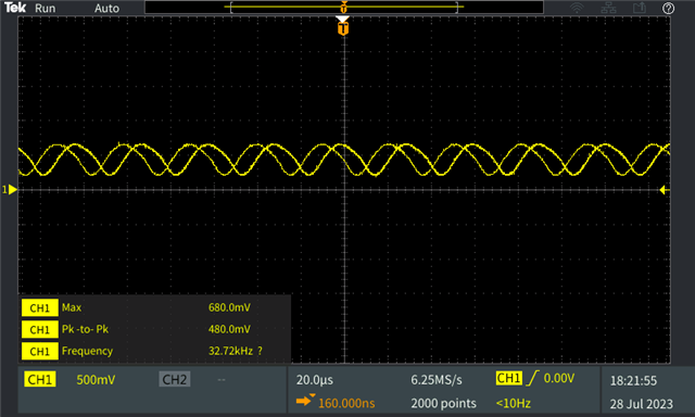
Whereas in msp430fr6898 board these points show 32.768khz sinusoidal wave withe same probe and settings.

Now what could be the issue

1. Wrong loading cap and crystal combination 

2. Damaged crystal

3. Damaged IC

  • 4. Bad soldering (when I activate lcd segment on this line I see 300hz sq wave, which says no bad soldering)

  • Nextday copied the example code again it worked. Then again the old code too worked fine. 

    Now i am not sure what made this working, yesterday i resoldered the crystal and loading caps but that did not worked then.

    one change i made yesterday was grounding the crystal casing. today i tested again after removing that casing grounding jumper but it still worked


    LFXINLFXOUT

    i have attached a picture(my pcb design is bad and soldering skills too bad) but now its working). Scope at these pins not recommended as probes capacitance will affect oscillator but it is easiest method rather than ACLK pin.

  • Hi Asim,

    This maybe cause by the crystal matching capacitor, when you use probe connect the pin , the capacitor will have some change(increase).

    Thus maybe this crystal be able to run succeeded.

    And you also need ensure crystal ground connect to MCU ground with a short wire.

    Thanks!

    Best Regards

    Johnson

  • Thanks Johnson,

    i have tested via probe earlier too, and now it runs without probe and with probe.

    in my case Crystal case grounding seems to have no effect as measured from ACLK pin, although some users in forum suggested and some denied about effect.

    I guess only possibility is bad soldering of the loading caps, or may be extra capacitance due to flux or dirt, but it was absolutely no oscillation.

    I was wondering what are the causes of oscillator failure, is there any specific wave shapes that represent failure cases. e.g. what will be wave shape in case of incorrect loading cap, or no loading cap, dry soldering. In my case there as no oscillation at all except a  20Mhz brust signal with a period of 0.1 seconds. and When i activate LCD 300hz noise can be seen at crystal pins.

  • Hi Asim,

    I don't get your point about this question:

    I was wandering what are the causes of oscillator, is there any specific wave shape to debug

    Do you would like to know the reason that Crystal run fail? I think this is cause by unreasonable matching capacitor.

    Thanks!

    Best Regards

    Johnson

  • Sorry my mistake. Corrected that line.

    Yes i want to know about crystal oscillator failure cases. 

    Will unmatched capacitor lead to no oscillation at all ? shifted frequency is obvious, even amplitude attenuation could be possible but i never expected so much attenuation that I could not detect any oscillation.

  • Hi Asim,

    Yes, I agree with you, unmatched capacitor maybe cause shifted frequency or amplitude, but for some corner, maybe cause run fail.

    Thanks!

    Best Regards

    Johnson

**Attention** This is a public forum