This thread has been locked.

If you have a related question, please click the "Ask a related question" button in the top right corner. The newly created question will be automatically linked to this question.

EVM430-F6779: How to bring those measured current and voltage values on the serial monitor in the PC ?

Part Number: EVM430-F6779

Hello TI team,

I am using evm430f6779 energymeter. I want to see the current and voltage measured values in the serial monitor of PC using UART. How can i do that ? where i can make changes in the energymeter code ?

From source code i didnt understand that how the measured current and voltage values are displayed on the screen of energymeter? 

Can you help me with that.

Thank you.

Regards,

Abhi

  • Hi Abhi,

    Do you want the raw format of the results? The results are converted to the DLT645 communication standard to talk to the GUI via UART. The emeter-dlt645.c found in the emeter-ng folder contains the communication protocol and packet creation that is being sent VIA UART.

    Otherwise the emeter-communication.c (and .h) files will have the UART ISR.

    If you want to view the results I suggest using the provided GUI (in the GUI folder change the calibration-config.xml file by editing and changing the COM port, simply searching for COM port will take you to the correct spot. Then run the calibrator.exe file), otherwise you would have to adjust the UART format in the files I mentioned above.

    Regards,
    Luke

  • Hello Luke,

    Can we replace the current sensors in the energymeter? do we need to make changes in the code ?

    If we are using the different type of current sensor which provides input value of 900 mV and 60 A  for this energymeter then what changes i have to make in the source code can you tell me ? Also in which file? where?

    As far as seen in the manual (Page 21), They have mentioned that voltage across current I1+ and current I1- must not exceed 930mV .But they havent mentioned anything about the current range . so can i use current sensor which gives input of 900mV and 60 A?? Do i have to make any changes in code because of this ?

    Another question: In our energymeter we are not using the display. So i have removed the code content which contains display regarding code. Does it affect any other values ?

    We are also removing the Aux vcc headers, DGND headers. and volatge monitor which is connected to pin 34 in the schematic of energymeter. Do i have to make changes in the code if we remove this components? or it will work without any problem?

    Thanks

    Regards,

    Abhi

  • Hi Abhi,

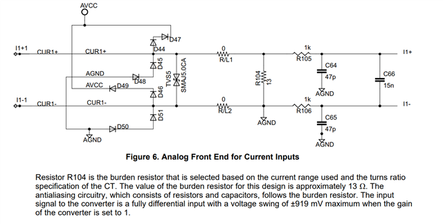
    1. You shouldn't need to adjust the code if you change the current sensors, but you may need to adjust the hardware design (Analog Front End for the current).
    2. You may want to adjust the gain depending on you actual input seen to the ADC
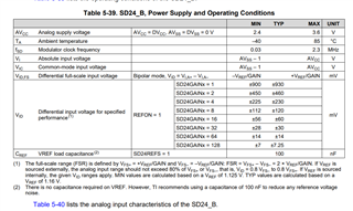
    3. The current reading is technically a voltage the reason the max is 930mV is due to this statistic in the datasheet so any adjustment to the gain will adjust your voltage range.
    4. The LCD is just a display, you can remove it and the code that calls updates to the LCD.
    5. The voltage monitor isn't connected originally so there should be no code change required. I will need to check if the code is setting up the Auxiliary supply. Considering we have jumpers to remove those options, you should be free to remove them.

    I recommend reading the Implementation of a Three-Phase Electronic Watt-Hour Meter to get an understanding of the design and code flow.

    Regards,
    Luke

  • Hello Luke ,

    Thank you very much for your answering the questions. 

    few more questions:

    In this case  how can the software distinguish if a 10A current sensor gives 930 mV output or a 65 A current sensor gives 930 mV output? There must be some sensor adaptation in the software. Thatswhat i think.

    Lets say If you measure 500 mV as output of the ADC what current does that mean?

    What will 930 mV output in your actual reference board mean? There must be some formula in the software that translates the voltage to a current value.

    I have seen manual twice but i didnt found anywhere the current value limit as ADC output. 

    Because of this current difference power value will change as well.

     Thank you very much .

    Have a nice day!!

    Regards,

    Abhi 

  • Hi Abhi,

    I'll have to get back to you on the software side of the current detection, but the analog front end is a large part of the current sensing.

    Regards,
    Luke

  • Hello Luke,

    Yes i look forward to your reply on software side.

    Thanks.

    Regrads,

    Abhi

  • Hi Abhi,

    The voltage range needs to be met to reach stay below the maximum allowed for the input. The current scaling factor is used as a multiplier to calibrate for your system as the relationship between current and voltage is linear. This can be found in emeter-structs.h current_sensor_nv_parms_s. I recommend using the GUI to adjust this value as the system needs to be calibrated for your CT.

    Regards,
    Luke

**Attention** This is a public forum