This thread has been locked.

If you have a related question, please click the "Ask a related question" button in the top right corner. The newly created question will be automatically linked to this question.

MSP430F5171: ACLK Mystery

Part Number: MSP430F5171

I'm using the watchdog timer and ACLK (standard WDT_ADLY_1000 configuration of the watchdog to provide 1 second interrupts) of this device for simple timekeeping, but I noticed significant deviation from exact time (more or less 3 minutes per day).

Initially I was using a 32.768kHz crystal on XIN XOUT, I changed this crystal for another one, played with load capacitances, but still had this important deviation.I put the fault on the crystal and bought a 25ppm reference clock. So now I feed the XIN with this clock (3.3V, perfect 32768Hz), but I'm still observing the same time deviation.

After quite a lot of investigation, I observed that the ACLK output is not correlated with the XIN signal; in other words it seems that whatever I do, the REF0CLK signal is used as ACLK.

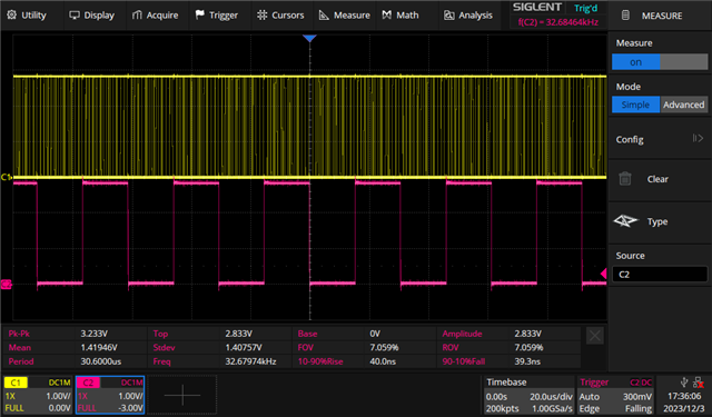
I attached two scope screenshots, the first one synced on XIN input, the second synced on ACLK output.

Of course, I configured USCTL4 with SELA at 0 to select XT1 CLK, and USCTL6 with XT1BYPASS, and confirmed these settings with the debugger.

So, at this point I have no clue on what could be wrong, any help would be greatly appreciated !

XIN Signal (yellow) ACLK (pink), XIN at 32768Hz

l

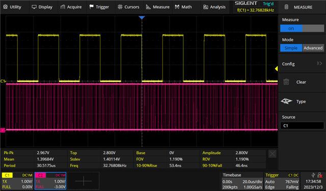
Same, but synched on ACLK, ACLK is at 32679Hz

  • /* --COPYRIGHT--,BSD_EX
     * Copyright (c) 2012, Texas Instruments Incorporated
     * All rights reserved.
     *
     * Redistribution and use in source and binary forms, with or without
     * modification, are permitted provided that the following conditions
     * are met:
     *
     * *  Redistributions of source code must retain the above copyright
     *    notice, this list of conditions and the following disclaimer.
     *
     * *  Redistributions in binary form must reproduce the above copyright
     *    notice, this list of conditions and the following disclaimer in the
     *    documentation and/or other materials provided with the distribution.
     *
     * *  Neither the name of Texas Instruments Incorporated nor the names of
     *    its contributors may be used to endorse or promote products derived
     *    from this software without specific prior written permission.
     *
     * THIS SOFTWARE IS PROVIDED BY THE COPYRIGHT HOLDERS AND CONTRIBUTORS "AS IS"
     * AND ANY EXPRESS OR IMPLIED WARRANTIES, INCLUDING, BUT NOT LIMITED TO,
     * THE IMPLIED WARRANTIES OF MERCHANTABILITY AND FITNESS FOR A PARTICULAR
     * PURPOSE ARE DISCLAIMED. IN NO EVENT SHALL THE COPYRIGHT OWNER OR
     * CONTRIBUTORS BE LIABLE FOR ANY DIRECT, INDIRECT, INCIDENTAL, SPECIAL,
     * EXEMPLARY, OR CONSEQUENTIAL DAMAGES (INCLUDING, BUT NOT LIMITED TO,
     * PROCUREMENT OF SUBSTITUTE GOODS OR SERVICES; LOSS OF USE, DATA, OR PROFITS;
     * OR BUSINESS INTERRUPTION) HOWEVER CAUSED AND ON ANY THEORY OF LIABILITY,
     * WHETHER IN CONTRACT, STRICT LIABILITY, OR TORT (INCLUDING NEGLIGENCE OR
     * OTHERWISE) ARISING IN ANY WAY OUT OF THE USE OF THIS SOFTWARE,
     * EVEN IF ADVISED OF THE POSSIBILITY OF SUCH DAMAGE.
     *
     *******************************************************************************
     * 
     *                       MSP430 CODE EXAMPLE DISCLAIMER
     *
     * MSP430 code examples are self-contained low-level programs that typically
     * demonstrate a single peripheral function or device feature in a highly
     * concise manner. For this the code may rely on the device's power-on default
     * register values and settings such as the clock configuration and care must
     * be taken when combining code from several examples to avoid potential side
     * effects. Also see www.ti.com/grace for a GUI- and www.ti.com/msp430ware
     * for an API functional library-approach to peripheral configuration.
     *
     * --/COPYRIGHT--*/
    //******************************************************************************
    //  MSP430F51x2 Demo - XT1 sources ACLK
    //
    //  Description: This program demonstrates using XT1 to source ACLK
    //  ACLK = LFXT1 = 32,768Hz	
    //  //* An external watch crystal between XIN & XOUT is required for ACLK *//	
    //
    //               MSP430F51x2
    //             -----------------
    //        /|\ |              XIN|-
    //         |  |                 | 32kHz
    //         ---|RST          XOUT|-
    //            |                 |
    //            |             P3.0|-->ACLK = ~10kHz
    //            |                 |
    //
    //   Bhargavi Nisarga
    //   Texas Instruments Inc.
    //   Dec 2009
    //   Built with CCS v4 and IAR Embedded Workbench Version: 4.21
    //******************************************************************************
    #include <msp430.h>
    
    void Port_Mapping(void);
    
    int main(void)
    {
      WDTCTL = WDTPW + WDTHOLD;                 // Stop WDT
      Port_Mapping();
    
      P3DIR |= BIT0;                            // P3.0=ACLK set out to pins
      P3SEL |= BIT0; 
      PJSEL |= BIT4+BIT5;                       // Port select XT1
    
      UCSCTL6 &= ~(XT1OFF);                     // XT1 On
      UCSCTL6 |= XCAP_3;                        // Internal load cap
      UCSCTL3 = 0;                              // FLL Reference Clock = XT1
    
      // Loop until XT2 & DCO stabilizes - In this case loop until XT1 and DCo settle
      do
      {
        UCSCTL7 &= ~(XT1LFOFFG + XT1HFOFFG + DCOFFG);
                                                // Clear XT1,DCO fault flags
        SFRIFG1 &= ~OFIFG;                      // Clear fault flags
      }while (SFRIFG1&OFIFG);                   // Test oscillator fault flag
      
      UCSCTL6 &= ~(XT1DRIVE_3);                 // Xtal is now stable, reduce drive strength
    
      UCSCTL4 |= SELA_0;                        // ACLK = LFTX1 (by default)
      
      __bis_SR_register(LPM3_bits);             // Enter LPM3
      __no_operation();                         // For debugger
    }
    
    void Port_Mapping(void)
    {
      __disable_interrupt();                    // Disable Interrupts before altering Port Mapping registers
      PMAPPWD = 0x02D52;                        // Enable Write-access to modify port mapping registers
      
      #ifdef PORT_MAP_RECFG                     
      PMAPCTL = PMAPRECFG;                      // Allow reconfiguration during runtime
      #endif  
      
      P3MAP0 = PM_TD1OUTH;
      
      PMAPPWD = 0;                              // Disable Write-Access to modify port mapping registers
      #ifdef PORT_MAP_EINT
      __enable_interrupt();                     // Re-enable all interrupts
      #endif  
    }
    

    Can you try this example code directly?

  • Hi Eason, 

    thanks for your help. Well, of course I could implement this, it would however require that I remove the reference clock I connected to XIN and re-solder a crystal; which is what I would do if I feel it helps solving the issue. However, I can't see how this modification would help solving my issue. My reference clock is low impedance and high precision, hence easy to trace, not so easy with a crystal on XIN.

    I have a clock input and I have a ACLK output (on port PJ.3), the issue seems that ACLK is not sourced by XT1 but by REF0CLK. I can't see how your example helps to find out why; can you please explain ?

  • I vaguely recall that on the F5 series XT1 doesn't re-engage as long as OFIFG is still set. [This also seems consistent with "NOTE: Fault Logic" on UG (SLAU208Q) p. 172.]

    Did you go through the clear-and-poll loop with OFIFG?

  • Right, I only cleared the XT1LFOFFG, clearing the OFIFG fixed the issue. Thanks !

  • Clearing all the oscillator fault flags fixed the issue, thanks for your help.

**Attention** This is a public forum