This thread has been locked.

If you have a related question, please click the "Ask a related question" button in the top right corner. The newly created question will be automatically linked to this question.

LP-MSPM0G3507: Timers(Timx):The timer peripherals can simultaneously support the Two independent channels for Output compare & Input capture ?

Part Number: LP-MSPM0G3507
Other Parts Discussed in Thread: SYSCONFIG, MSP430F5324, MSPM0G3507

Hi Sir

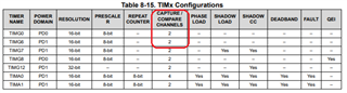
     A Timer has only one counting register, but if it supports two channels, can I set TimG6 CCR0 as the comparison output and CCR1 as the capture input at the same time?

   
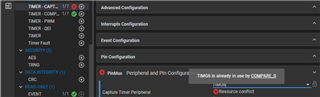
An error will occur when setting in Sysconfig.

Thanks.

  • The problem is that when it captured, it will reset the timer by default, which will cause the PWM output to be not right. That is why we don't enable it in sysconfig. If you want to realize this, you may need to handle the zero cross problem for the counter.

  • hi Eason

    we use MSPM0 G3507 build our temperature controller project, i just need a simple function, in  TIMG8 one CCR as compare another as capture, i think this is a basic application in mcu and we use this method in MSP430F5324 but in sysconfig we got problem(like wilson picture).

    my application is CCR0 as compare function and toggle output pin, CCR1 as captrure function, when capture pin get signal  capture the counter value to CCR1 and timer counter continue running until i stop the timer.

    Can G3507 achieve this function?

  • The short answer is: Yes, you can configure one CCR for compare and the other for capture. In my application I use one channel for capture (frequency counting) and the other as a timeout-compare for the capture. I use continuous counting (Up mode to 0xFFFF) and differencing rather than the LCOND recommendation in TRM Sec 25.2.3.1.2.2 ("Period Capture") due to Erratum TIMER_ERR_01.

    Having a common time base (CTR register) puts some limitations on how you can use the channels, but these are probably not much different from what you're working with in the F5324.

    I don't know much about sysconfig, so I defer to Eason on that.

  • hi Bruce

    thanks for your reply, according to your describe, i find there are two problems i need to check

    (1) you don't use sysconfig to configure your peripherals, i guess you use the SDK drivelib and coding directly, am i right?

    (2) capture function has bug, when i use timer zero event or load event the capture value always zero or load value, am i right?

  • 1) I write the registers directly. If there are limitations in sysconfig or the driverlib I don't know about them.

    2) Yes. The model for "Period Capture" (also "Pulse Width Capture", Sec 25.2.3.1.2.3) uses ZCOND to zero the CTR after each capture, so you don't have to difference consecutive capture values. Except that, due to Erratum TIMER_ERR_01 [Ref Errata sheet (SLAZ742A) p. 15], that method doesn't work, so you have to do the differencing after all. This is the same as what (I suppose) you're doing with the MSP430 since TimerA/TimerB don't have a ZCOND-like mechanism.

  • Hi Bruce

    (1) tough guy!

    (2) if my application need zero event(overflow count) with capture function, i guess i have trouble right ?

    i saw the M0G3507 in ordering list of TI website, my distributor told me that is MP product, do you know

    if they have fixed this issue in mass production products?

  • (2) In Up mode, the CTR is automatically zeroed (with a "Z" interrupt trigger, effectively TAIFG) when it counts to the LOAD value; that does work. The ZCOND can trigger this zeroing from other events; that's the one that has trouble.

    The Erratum is for production device rev B, i.e. an "M" (production), not an "X" (pre-production) device. I actually watched it happen on my Rev B device.

  • Hi Bruce

    thanks for your reply, let's wait for TI employee opinion.

  • Hi, the bug is for MP product. The bug doesn't means the zero event and overflow count event don't work. It means the counter capture value saved in TIMx.CC is not right. It doesn't affect the counter. It only affect the capture register(TIMx.CC).

    If you want to realize PWM out + capture. You can't use the examples in the driverlib, because it will reset the counter after the capture event.

  • Hi Eason

    my application need use zero event to calculate overflow number and getting correct capture value between overflow7~ overflow8, so correct capture value is very important to us.

    is that meaning i can't use this mcu  in my project?

    Does TI have any plans or schedule to fix this bug?

  • Just don't use the ZCOND feature along with capture. You're not using it now, since it doesn't exist on the MSP430. I only mentioned it since the TRM will recommend that you use it (for period/duty measurement), so you need to ignore that.

    Unsolicited: You haven't described your application, so this may not be relevant: If you want to capture on both (rising + falling) edges, you (most likely) need to use both channels for capture -- one for rising edge and the other falling. You can trigger on "either", but there's no mechanism (that I found) for deducing which edge triggered; on the MSP430 you can read CCI or the PxIN register to do this.

  • Hi Bruce

    current project is MSPM0 G3507 not MSP430.

    if i don't use ZCOND or LCOND, then how do I calculate overflow count?

  • I suppose that you're currently counting TAIFG interrupts. Instead, you would count "L" interrupts (GPTIMER_CPU_INT_MIS_L_SET). [Sorry I think I said "Z" before, but "L" is what my code (different application) says.]

    I thought you said you wanted to re-implement something you're currently doing with the MSP430, where you don't need the ZCOND feature.

  • Hi Bruce

    thanks for your opinion, i offer my application note, this application note running in MSP430F5324 very well,

    can you help me check if this can be used in MSPM0G3507,  My original thought was

    TA2=TIMG8

    TA2CCR0=>TIMG8.CC0   // as cpmpare

    TA2CCR1=>TIMG8.CC1   //  as capture

    TAIE=>zero event               // overflow count

    timer_action_flow.pdf

  • You can use zero event and load event in your MSPM0. The unavailable function is this: you can't let MCU to reflash the counter after you get a capture event. You need to keep ZCOND and LCOND to be 0. 

    In our exmaple code, the counter is updated in the interrupt. For your applicaiton, you can remove the counter update when you meet a capture event. Seen your pdf, I think you can realize what you want.

    For the bug, it will be fixed in the furture devices. For this device, currently there is no plan to fix it.

  • I agree with Eason -- I don't see anything here that TIMG can't do.

    For OUTMOD, use CCACT:CUACT. For enabling/disabling/clearing interrupts, use IMASK/MIS/ICLR. You don't want LCOND/ZCOND. I think you also don't need/want shadow registers (if that question comes up).

  • Hi Eason and Bruce

    great answer, thanks for your help.

**Attention** This is a public forum