- Ask a related questionWhat is a related question?A related question is a question created from another question. When the related question is created, it will be automatically linked to the original question.


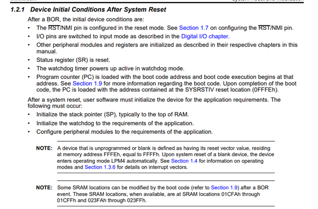
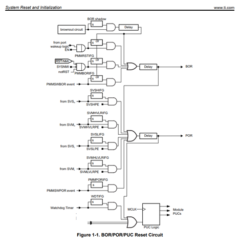
RST/NMI BOR and PMMSWBOR reset all registers and make MCU guarantee recover to normal state or not?

As i have issue related to the PMM module (not found exactly root cause yet).
So, i would like to confirm that RST/NMI BOR and PMMSWBOR reset all registers and make MCU recover to normal state?
More details steps following.
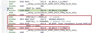
Steps:
1) Supply DVCC to 3.3 V
2) Setting Vcore = 3 and then set MCU Clock from 1 Mhz to 25 Mhz.
3) Drop voltage to 2.2 V (below recommend operating voltage).
4) Something abnormal occur due to MCU running out of operating range
5) Increase voltage 2.2 V back to 3.3 V
6) Source code make PMMSWBOR
Does PMMSWBOR and make MCU recover to normal state.
I think the BOR may not guarantee all thing recover right?
(it only the power cycle of DVCC to 0 V and then resupply DVCC)

**Attention** This is a public forum