This thread has been locked.

If you have a related question, please click the "Ask a related question" button in the top right corner. The newly created question will be automatically linked to this question.

MSP430FR2310: I/O status under low voltage

Part Number: MSP430FR2310

When the VCC voltage is 2V, use pin P1.5 to output a high level to drive a MOSFET, and then enter the LMP4 state. When the VCC voltage drops by 1.5V, can P1.5 still maintain the output high level?

We understand that it is possible for others to use PIC16LF1832, and we want to use it to achieve the same function.

When powered by solar energy, what is the reset current of this IC when the voltage is 2V?

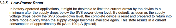
In practical applications, after resetting FR2310, pin P1.5 outputs a high level and immediately enters LMP4 state. Is there any way to reduce the reset current?

Because our solar panels can only provide a current of 10uA, at 1.9V, we found that FR2310 periodically resets, causing voltage instability. Once the reset is successful, 10uA can make it work stably.

  • Hi Yu,

    When the VCC voltage is 2V, use pin P1.5 to output a high level to drive a MOSFET, and then enter the LMP4 state. When the VCC voltage drops by 1.5V, can P1.5 still maintain the output high level?

    When VDD drops below the SVS- power down voltage threshold, the device essentially is in reset and there is no guarantee the IO pins will maintain their current states.  For your application, P1.5 will most likely default to an input pin and no longer control the mosfet.

    When powered by solar energy, what is the reset current of this IC when the voltage is 2V?

    While in reset, it is possible to see higher currents, as noted below.

    Because our solar panels can only provide a current of 10uA, at 1.9V, we found that FR2310 periodically resets, causing voltage instability. Once the reset is successful, 10uA can make it work stably.

    As mentioned above, if VDD drops below SVSH- the MSP will reset, causing the increase in current.

    Ok - one solution would be to increase the size of the 'tank' capacitor (typically 4.7uf - 10uf).  You might try 47uf or 100uf as an experiment.

**Attention** This is a public forum