


Other Parts Discussed in Thread: LMP91000, MSP430FR2355,
I have been using the LMP91000 in my Electrochemical circuits for a while and I really like its performance. We have a new project where we decided to implement the potentiostat circuit using the SAC-L3 peripherals provided inside the MSP430FR2355. I noticed a significant amount of low frequency noise on my sensor output, which is not present on the LMP91000 with the same sensor connected. I've run a number of tests over the past week to try and figure out what is the source of the noise and it seems to be a combination of the SAC with the sensor. I would be happy to elaborate on the tests I have done and what I've found if anybody asks or thinks it would be helpful. I have found some things to help reduce noise on the SAC implementation (like changing load resistor from 10 Ohms to 100 Ohms), but they all sacrifice response time, which is not ideal for this particular application and I'm not yet convinced it's necessary as I'm assuming I'm overlooking something. Is the noise difference between the LMP91000 and the SACs on the FR2355 to be expected? Can anyone point to the particular spec which may be the cause of this variation?
I have attached snapshots of the schematic implementation of the LMP91000 as well as the SAC circuit, along with a scope capture of the noise for each. I have also attached a C file which can be executed on a DevKit to prove re-producibility.
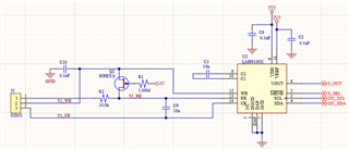
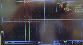
LMP91000 Schematic and Scope Capture (LMP91000 configured for 10 Ohm Load, 120k Ohm Gain, 50% Reference, 0% Bias, 3-Lead Echem Mode)
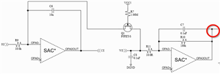
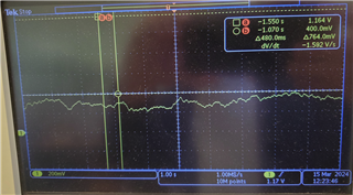
SAC Schematic and Scope Capture (DAC set to 0.3V Reference on Non-Inverting inputs using internal 2.5V reference, High Power High Speed Mode, General Purpose)
EXP-MSP430FR2355 DevKit Code Example
#include "driverlib.h"
#include <msp430.h>


static void _SAC_init_gpio(void)
{
    //Initialize the SAC GPIOs
    MAP_GPIO_setAsPeripheralModuleFunctionOutputPin(GPIO_PORT_P1,
                        GPIO_PIN1 | GPIO_PIN2 | GPIO_PIN3 | GPIO_PIN5 | GPIO_PIN6 | GPIO_PIN7,
                        GPIO_TERNARY_MODULE_FUNCTION);
//    MAP_GPIO_setAsPeripheralModuleFunctionOutputPin(GPIO_PORT_P3,
//                        GPIO_PIN5 | GPIO_PIN6 | GPIO_PIN7,
//                        GPIO_TERNARY_MODULE_FUNCTION);
}

static void configure_DAC_SACX(uint16_t baseaddress, uint16_t dac_setting)
{
    //Select 2.5V internal Vref as SAC0 DAC reference
    MAP_SAC_DAC_selectRefVoltage(baseaddress, SAC_DAC_SECONDARY_REFERENCE);
    //Set SAC0 DAC output = 0.3v
    MAP_SAC_DAC_setData(baseaddress, dac_setting);
    //Enable SAC0 DAC
    MAP_SAC_DAC_enable(baseaddress);
}

//static void configure_PGA_SACX(uint16_t baseaddress, uint16_t mode, uint16_t gain)
//{
//    //Select PGA mode
//    MAP_SAC_PGA_setMode(baseaddress, mode);
//    //Set PGA gain
//    MAP_SAC_PGA_setGain(baseaddress, gain);
//}

static void configure_OPAMP_SACX(uint16_t baseaddress, uint16_t positive_source, uint16_t negative_source)
{
    //SAC_OA_POWER_MODE_LOW_SPEED_LOW_POWER
    //SAC_OA_POWER_MODE_HIGH_SPEED_HIGH_POWER
    //Setup OA0
    MAP_SAC_OA_init(baseaddress, positive_source, negative_source);
    //Select low speed and low power mode
    MAP_SAC_OA_selectPowerMode(baseaddress, SAC_OA_POWER_MODE_HIGH_SPEED_HIGH_POWER);
    //Enable OA
    MAP_SAC_OA_enable(baseaddress); //Enable SAC
}


int main(void) {

    MAP_WDT_A_hold(WDT_A_BASE);


//    P1DIR |= BIT0;                       // Set P1.0 direction as output
//    P1OUT &= ~BIT0;                      // Set P1.0 output low

    // Disable GPIO power-on default high-impedance mode to activate
    // previously configured port settings
    MAP_PMM_unlockLPM5();
    MAP_PMM_enableInternalReference();
    MAP_PMM_selectVoltageReference(PMM_REFVSEL_2_5V);
    MAP_PMM_enableTempSensor();
    //Poll until internal reference settles
    while(!MAP_PMM_getVariableReferenceVoltageStatus());

    // Configure LED1 (P1.0)
    MAP_GPIO_setAsOutputPin(GPIO_PORT_P1, GPIO_PIN0);

    _SAC_init_gpio();

    //DAC
//    configure_DAC_SACX(SAC0_BASE, 491);
//    configure_DAC_SACX(SAC1_BASE, 491);
    //SAC
    //SAC_OA_POSITIVE_INPUT_SOURCE_EXTERNAL
    //SAC_OA_POSITIVE_INPUT_SOURCE_DAC
    configure_OPAMP_SACX(SAC0_BASE, SAC_OA_POSITIVE_INPUT_SOURCE_EXTERNAL, SAC_OA_NEGATIVE_INPUT_SOURCE_EXTERNAL);
    configure_OPAMP_SACX(SAC1_BASE, SAC_OA_POSITIVE_INPUT_SOURCE_EXTERNAL, SAC_OA_NEGATIVE_INPUT_SOURCE_EXTERNAL);
    //ENABLE
    MAP_SAC_enable(SAC0_BASE);
    MAP_SAC_enable(SAC1_BASE);

    // Configure ADC to sample SAC_OA output (A1)
//    ADCCTL0 &= ~ADCENC;                 // Disable ADC
//    ADCCTL0 = ADCSHT_2 | ADCON;         // ADCON, S&H=16 ADC clks
//    ADCCTL1 = ADCSSEL_0 | ADCDIV_0 |    // ADCCLK = MODCLK, divide by 1
//              ADCCONSEQ_0 |             // Single Channel, single conversion,
//              ADCSHP | ADCSHS_0;        // Pulse sample mode, SW trigger
//    ADCCTL2 = ADCRES_2;                 // 12-bit conversion results
//    ADCMCTL0 = ADCINCH_1 |              // A1 ADC input select = SAC output
//               ADCSREF_0;               // Vref = DVCC
//    ADCIE = ADCIE0;                     // Enable ADC conv complete interrupt


    while(1)
    {
//        ADCCTL0 |= ADCENC | ADCSC;          // Sampling and conversion start
//        __bis_SR_register(LPM0_bits | GIE); // Enter LPM0, ADC_ISR will force exit
//        __no_operation();                   // For debug only
//
//        if (adcResult > 0x7FF)              // OA output > 1/2 VREF
//        {
//            P1OUT |= BIT0;                  // Set P1.0 LED on
//        }
//        else
//        {
//            P1OUT &= ~BIT0;                 // Clear P1.0 LED off
//        }
        MAP_GPIO_toggleOutputOnPin(GPIO_PORT_P1, GPIO_PIN0);
        __delay_cycles(5000);
    }
}


// ADC interrupt service routine
//#if defined(__TI_COMPILER_VERSION__) || defined(__IAR_SYSTEMS_ICC__)
//#pragma vector=ADC_VECTOR
//__interrupt void ADC_ISR(void)
//#elif defined(__GNUC__)
//void __attribute__ ((interrupt(ADC_VECTOR))) ADC_ISR (void)
//#else
//#error Compiler not supported!
//#endif
//{
//    switch(__even_in_range(ADCIV,ADCIV_ADCIFG))
//    {
//        case ADCIV_NONE:
//            break;
//        case ADCIV_ADCOVIFG:
//            break;
//        case ADCIV_ADCTOVIFG:
//            break;
//        case ADCIV_ADCHIIFG:
//            break;
//        case ADCIV_ADCLOIFG:
//            break;
//        case ADCIV_ADCINIFG:
//            break;
//        case ADCIV_ADCIFG:
//            adcResult = ADCMEM0;                    // Read ADC memory
//            __bic_SR_register_on_exit(LPM0_bits);   // Exit from LPM
//            break;
//        default:
//            break;
//    }
//}

