
- Ask a related questionWhat is a related question?A related question is a question created from another question. When the related question is created, it will be automatically linked to the original question.
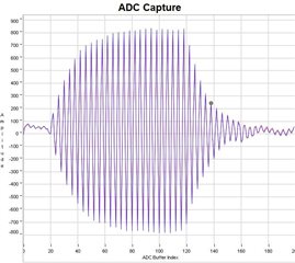
I have a couple of questions but first I wanted to start with a description of the goal of the project. Currently we are trying to make a flow detector. Ideally, we would like the system to work from .08 gph to 100 gph or as low as possible if we can't get down to the .08 gph range. Ideally the fluid in the line could be almost anything but for my development I am using water and sodium hypochlorite. We are wanting a clamp on solution to not add any new potential leak points. To start we are able to use Procom PSC.0M022302H2AD0-B0 in diagonal orientation over a 1/4" ID polypropylene tubing. The ADC look good but when running we can't really see any difference between No Flow and low flow (~.25 gph).
So:
Question #1.
We working theory is that since the sensors are so close ~1.9 cm the Time of Flight is almost the same for the No Flow(Zero Flow) and the low rate that would be able to detect flow better if we lengthen the Time of Flight. Is this a correct assumption?
Question #2.
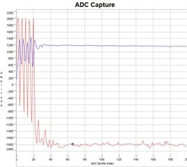
Assuming question 1 is correct, we stared to work on V or W configuration. We have one transducer fixed and we can move the other transducer as needed to make a "V" or a "W" path. When working on the adjustable housing we also made the material under the traducers and what is reflecting the signal back. For the material that we are trying to pass through, we are using HDPE 1/8" thick and are reflecting the signal back with 1/8" cold roll steel. However, that signal from the EVM430-FR4067 does not seem to have enough power to make the V let alone the W. When looking at the technical documents, I found XXXX had the OPA838 we recommended. I have tried to bread board these initially on the CH0 and CH1 "out" side with no luck. I went back to the document and saw they recommended the op amps to be on the CH0 and CH1 "in" side. I am having no luck getting a good-looking ADC Capture when the Op Amps are in the circuit. I even removed the Rg resistor so it should just be a follower. I even went back to the diagonal housing, and I can't get an ADC capture with the op amp. Is there a reference design for adding Op Amps to the transducers that I have missed?
Thank you in advance for any assistance.
**Attention** This is a public forum


