Other Parts Discussed in Thread: EVM430-FR6047, , TS5A3357
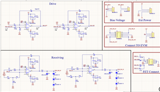
Hello everyone, recently I wanted to use EVM430-fr6047 to design an ultrasonic flowmeter for use on stainless steel pipes, but the signal is weak, I noticed this design solution, TIDA-01486, which is a better match for my needs, so I proceeded to use this solution, but I encountered a problem, the following is my schematic diagram。
My first question is, as a newbie, I don't know if I should also use an analog switch when I only have a pair of transducers. I noticed that the analog switch is used in the TIDA-01486 that you guys have given, and in one of the answers it was mentioned that this analog switch is to protect the USS module of the MSP430.https://e2e.ti.com/support/microcontrollers/msp-low-power-microcontrollers-group/msp430/f/msp-low-power-microcontroller-forum/1111257/msp430fr6047-external-amplifier-to-increase-the-drive-voltage-and-amplify-received-signal/4119095?tisearch=e2e-sitesearch&keymatch=EVM430-FR6047%2525252520metal%2525252520pipe#4119095 But as far as I can see, I don't know how he is protecting it, I think it is just for switching between pair1 and pair2. please answer for me, thank you very much.
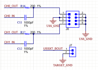
My second question is, on the EVM430-6047 development board, the input and output pins of the chip belonging to the same transducer are connected together, for example, ch0_in and ch0_out, as shown in the circuit diagram below, so when I connect them, do I need to solder the corresponding pins on the op-amp board to the R16 and C11 of the EVM board directly instead of connecting them to the row of pins?