Other Parts Discussed in Thread: LM35
I'm trying to use the temperature provided by the internal sensor of the MSP430FR6928. I followed the recommendations shown in one "Out of the Box" application for a similar device.
In the configuration of the ADC12_B (routine that runs only once at the beginning of the code, I performed the following actions (I'm just including those instructions that are related to the temperature:
void InitADC12_B(void) {
// 1. I created this constant (a float) that is calculated only once during the program:
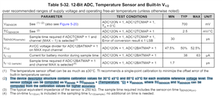
Tmprtr_factor = ((85-30) * 10) / (float)( (CALADC12_12V_85C - CALADC12_12V_30C) * 10);
// 2. I used the 1.2V reference, so this is the setup I used:
while (Ref_A_isRefGenBusy(REF_A_BASE))
;
Ref_A_setReferenceVoltage(REF_A_BASE, REF_A_VREF1_2V); // Select Internal Reference ref = 1.2V
Ref_A_enableReferenceVoltage(REF_A_BASE); // Internal Reference ON
Ref_A_enableTempSensor (REF_A_BASE);
while(!Ref_A_isVariableReferenceVoltageOutputReady(REF_A_BASE))
;
// I found 2 examples that set the reference ... one used Ref_A_isRefGenBusy() and the other used Ref_A_isVariableReferenceVoltageOutputReady() ... from the description of these functions in the DriverLib Manual I couldn't understand which one to use ... so I used both.
// 3. I'm using the 5MHz clock as the ADC12_B clock, so I used 256 and 512 sampling cycles. This seems to be plenty. I couldn't find a difference in the result.
ADC12_B_setupSamplingTimer(ADC12_B_BASE, // These are the bits SHT0x in ADC12CTL0 register
ADC12_B_CYCLEHOLD_512_CYCLES,
ADC12_B_CYCLEHOLD_16_CYCLES, // This is the default value 5MHz is divided at least by 4
ADC12_B_MULTIPLESAMPLESENABLE); // No need to apply a trigger for each conversion.
ADC12_B_initParam initParam = {0}; // initParam is the instantiation of the Structure ADC12_B_initParam
initParam.sampleHoldSignalSourceSelect = ADC12_B_SAMPLEHOLDSOURCE_SC; // Program code will start the conversion (SC) (default)
initParam.clockSourceSelect = ADC12_B_CLOCKSOURCE_ADC12OSC; // MODOSC 5 MHz from the CS will be the Converter clock (default)
initParam.clockSourceDivider = ADC12_B_CLOCKDIVIDER_1; // This divider is also the default
initParam.clockSourcePredivider = ADC12_B_CLOCKPREDIVIDER__1; // This is also the divider
initParam.internalChannelMap = ADC12_B_TEMPSENSEMAP; // Bring out the internal Sensor that monitors die temperature
//initParam.internalChannelMap = ADC12_B_NOINTCH; // Internal channel is used(e.g. Temp) so this parameter is commented out
ADC12_B_init(ADC12_B_BASE, &initParam);
// 4. The result of the conversion for the temperature goes to memory 4:
// Memory 4 Internal Temperature Sensor
configureMemoryParam.memoryBufferControlIndex = ADC12_B_MEMORY_4;
configureMemoryParam.inputSourceSelect = ADC12_B_INPUT_TCMAP; //configureMemoryParam.inputSourceSelect = Temperature
configureMemoryParam.refVoltageSourceSelect = ADC12_B_VREFPOS_INTBUF_VREFNEG_VSS;
configureMemoryParam.endOfSequence = ADC12_B_ENDOFSEQUENCE;
configureMemoryParam.windowComparatorSelect = ADC12_B_WINDOW_COMPARATOR_DISABLE;
configureMemoryParam.differentialModeSelect = ADC12_B_DIFFERENTIAL_MODE_DISABLE;
ADC12_B_configureMemory(ADC12_B_BASE, &configureMemoryParam);
// 5. Start the conversion cycle and when the interrupt shows up ... this is what I do:
Raw_Tmprtr = (ADC12_B_getResults(ADC12_B_BASE, ADC12_B_MEMORY_4) - CALADC12_12V_30C);
Last_die_Tmprtr = 10 * (long)Raw_Tmprtr * Tmprtr_factor + 300;
As can be seen, the temperature result, multiplied by 10, ends up in Last_die_Tmprtr ... This result is saved into an array that eventually is moved to a PC.
Perhaps I am wrong on this one, but I thought that it was more efficient to perform a multipication rather than a division inside the interrupt.
Timing is not a problem. Every 2 sec, the uController performs 5 measurements and goes back to do nothing.
My question is: Temperature measurements are performed every 2 seconds. And the results can be closed to each other, but some times they
"jump" up to 2 degreeC. The board I'm using for development is almost empty. It contains only the uController, decouplig capacitors, a connector to program the part and to give access to a serial port and a reference voltage generator that provides 3.3V to power up the part. Most of the tests are performed using the voltage provided by programmer. I'm using several inputs of the A2D, but at this point, they have no signal and are connected to ground through 10K resistors. Before jumping into building a digital filter I would like to know if my results are reasonable or I am having some electrical or firmware problem that I must correct. I have tested the other channels that monitor external signals and they look very reasonable to me. But I am using an external reference of 3.3V for all these other channels/measurements.
Regards