- Ask a related questionWhat is a related question?A related question is a question created from another question. When the related question is created, it will be automatically linked to the original question.

I have an old MSP430 design that started with earlier CCS versions 4 or 5. The devices was in-use and has worked for years, and suddenly stopped responding.
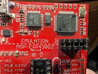
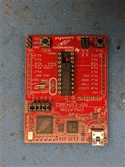
It is using theMSP430G2231 as shipped on the Launchpad board with USB interface.
Now I've updated to CCS 6.1.3 on Windows. The code I'm trying to debug is unchanged.
When I try to run the debugger, I get "Error initializing emulator: Could not find MSP-FET430UIF on specified COM port"
The port enumerates in Device Manager, and is reported as "MSP430 Application UART"
This error has been around sporadically for years, but I've never found an actual root cause or solution.
I've tried replacing the Launchpad with another one but get the same error.
The code is based on the early example code from when the Launchpad was introduced:
//******************************************************************************
// MSP430G2xx1 Demo - Timer_A, Ultra-Low Pwr UART 9600 Echo, 32kHz ACLK
// ACLK = TACLK = LFXT1 = 32768Hz, MCLK = SMCLK = default DCO
// //* An external watch crystal is required on XIN XOUT for ACLK *//
//
// MSP430G2xx1
// -----------------
// /|\| XIN|-
// | | | 32kHz
// --|RST XOUT|-
// | |
// | CCI0B/TXD/P1.1|-------->
// | | 9600 8N1
// | CCI0A/RXD/P1.2|<--------
//
// D. Dang
// Texas Instruments Inc.
// October 2010
// Built with CCS Version 4.2.0 and IAR Embedded Workbench Version: 5.10

**Attention** This is a public forum