Tool/software:
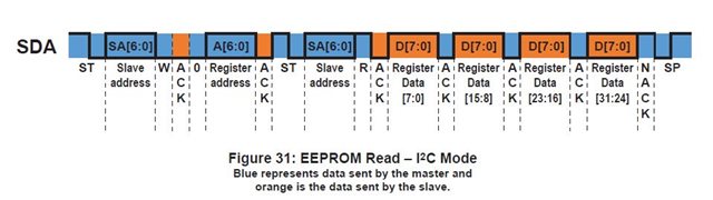
I am trying to implement I2C communications with a slave IC. The slave device is ACS37800 Power monitoring IC. The task is to
acheive an I2C read operation with the above format .
The use case requires a repeated start condition, I could only find example codes for conventional I2C slave read, (i.e without repeated starts).
Can a sample code to implement repeated start be provided for MSP430F2619.
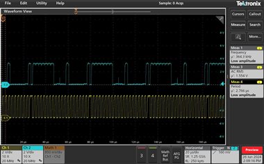
Here is what I tried to implement [ SCL @ 143KHz]
#include <msp430.h>
// Define global variables
unsigned char RXData, Master_RX, TXByteCtr = 0, RXByteCtr = 4; // RXByteCtr set to the number of bytes to read
int i,c=0;
unsigned char RXDataarr[15]={1,2,3,4,5,6,7,8,9,10,11,12,13,14,15};
// Function prototypes
void Master_TX_to_RX_Slave(void);
void MasterUSCIB0TX(void);
int main(void)
{
WDTCTL = WDTPW + WDTHOLD; // Stop WDT
P3SEL |= 0x06; // Assign I2C pins to USCI_B0
while (1)
{
Master_TX_to_RX_Slave(); // Perform Master TX to RX Slave communication
__bic_SR_register(GIE);
// Clear general interrupt enable
}
}
// USCI_B0 Data ISR1
#if defined(__TI_COMPILER_VERSION__) || defined(__IAR_SYSTEMS_ICC__)
#pragma vector = USCIAB0TX_VECTOR
__interrupt void USCIAB0TX_ISR(void)
#elif defined(__GNUC__)
void __attribute__((interrupt(USCIAB0TX_VECTOR))) USCIAB0TX_ISR(void)
#else
#error Compiler not supported!
#endif
{
if (Master_RX == 0)
{
if (TXByteCtr == 1)
{ __delay_cycles(50);
UCB0TXBUF = 0x20; // Send the register address
TXByteCtr--;
}
else
{
Master_RX = 1;
//c=1;
UCB0CTL1 &= ~UCTR; // Switch to RX mode
UCB0CTL1 |= UCTXSTT; // Send repeated start condition
}//do
//{
}
if (Master_RX == 1)
{
if (UCB0CTL1 & UCTXSTT) // Ensure start condition was sent
return;
RXDataarr[c] = UCB0RXBUF;
c++;
if(c==8)
{
UCB0CTL1 |= UCTXSTP; // Send stop condition
IE2 &= ~UCB0TXIE;
IE2&= ~UCB0RXIE;
c=0;
}
}
}//isr
// Function to initiate Master TX to RX Slave communication
void Master_TX_to_RX_Slave(void)
{
MasterUSCIB0TX();
__bis_SR_register(GIE); // Enable general interrupts
TXByteCtr = 1; // Load TX byte counter
while (UCB0CTL1 & UCTXSTP); // Ensure stop condition was sent
UCB0CTL1 |= UCTR + UCTXSTT; // I2C TX, start condition
// Add a timeout mechanism to prevent infinite loop
while (UCB0CTL1 & UCTXSTT);
__bis_SR_register(GIE); // Enable interrupts
while (UCB0CTL1 & UCTXSTP); // Ensure stop condition was sent
}
// Function to configure USCI_B0 for Master transmission
void MasterUSCIB0TX(void)
{
UCB0CTL1 |= UCSWRST; // Enable software reset
UCB0CTL0 = UCMST + UCMODE_3 + UCSYNC; // I2C Master, synchronous mode
UCB0CTL1 = UCSSEL_2 + UCSWRST; // Use SMCLK, keep software reset
UCB0BR0 = 7; // Set SCL frequency 1Mhz / 7 ~~ 143Khz
UCB0BR1 = 0;
UCB0I2CSA = 0x7F; // Set slave address (adjust as needed)
UCB0CTL1 &= ~UCSWRST; // Clear software reset, resume operation
Master_RX = 0; // Initialize Master_RX flag
IE2 |= UCB0TXIE + UCB0RXIE ; // Enable TX and RX interrupts
}
The above code iterates through the ISR 9 times to receive 4 bytes of slave data. The transmit portion is more understandable but I couldn't figure out why the receive portion
needs to iterate 9 times to receive 4 bytes of slave data. when it should theoritically iterate only 4 times. I got this value of 9 via trial and error as 4 iterations only
yielded less than 4 bytes and ended in a premature termination of I2C communications.
Even after receiving 4 Bytes, the RXIFG flag remains SET and this is also an area of concern as i am expecting to terminate communications after 4 Bytes.
Any kind of solution or advice would be very helpful regarding why this issue is occuring.
Regards,
Anand VS