This thread has been locked.

If you have a related question, please click the "Ask a related question" button in the top right corner. The newly created question will be automatically linked to this question.

MSP430FR2676: MSP430FR2676

Part Number: MSP430FR2676
Other Parts Discussed in Thread: CAPTIVATE-PGMR, CAPTIVATE-FR2676, CAPTIVATE-BSWP, CCSTUDIO, UNIFLASH

Tool/software:

Hello TI Support,

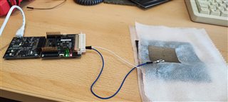
I have ordered the following components for capacitive measurement:

  • CAPTIVATE-PGMR Hardware programming tool
  • CAPTIVATE-FR2676 Evaluation board
  • CAPTIVATE-BSWP Evaluation board

For software, I have already downloaded Java, the Design Center GUI, and Code Composer Studio (CCSTUDIO).

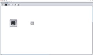
I have connected all the parts to perform the measurement. I can see that the device is getting connected in the GUI, but I am not able to see any graphs or measurements. Is it possible to have an online meeting to discuss this issue?

Please let me know your availability, and I will send you an online BBB meeting request.

Kind regards,

Sushant

  • Hello Sushant,

    I believe the CAPTIVATE-FR2676 EVM should be pre-programmed with the "out of box" example, so one way to check is with the BSWP board connected, if you touch any of the sensors (buttons, slider or wheel) you should see a couple of LEDs on for lower right side of the CAPTIVATE-FR2676 board light up.  If not, then the EVM will need to be programmed. You can do this two ways.

    First you can use Uniflash to reprogram the board.  You can either download Uniflash and install (here is the link) or you can run it from the web (same link).

    The image you need to use is located locally on your computer at:

    C:\ti\msp\CapTIvateDesignCenter_1.83.00.08\CapTIvateDesignCenter\example_projects\CaptivateDesignCenterWorkspace\TI_Examples\FR2676_CAPTIVATE-BSWP\demo_bin

    Choose either FR2676_CAPTIVATE-BSWP-Demo.txt. or FR2676_CAPTIVATE-BSWP-Demo.out

    Try that and let me know what you find.

  • Hello Dennis,

    Thank you for your email.

    The kit is working properly. This is my first time using this kit, and I still need to optimize the configuration for self-developed capacitive measurement.

    Could you please let me know if I can use connector cables instead of the evaluation board to connect our sensors for evaluation? If yes, which type of cable should I order?

    What are the steps to perform these measurements? Is block-level coding sufficient?

    Can we also use the same kit to perform resistive sensor measurements using the same configuration?

    Kind regards,

    Sushant

  • Hi Sushant,

    You can absolutely use wires connected to the large 48-pin connector on the CAPTIVATE-FR2676 EVM PCB.  That's how lots of customers do proof of concept prototyping and don't bother creating a PCB until later.  They use copper tape to create their sensor and connect to the EVM using wires.

    It doesn't matter what you use for wiring.  Any wire that plugs into the connector securely.   The one downside to doing it this way is the wires you use are now part of the sensor, meaning they are sensitive to your hand or other objects.  Also, when the system performs a calibration to establish the working baseline measurements (this happens after power on or reset), if you move the wires, the baseline will no longer be correct and the system will not perform as expected.

    What are the steps to perform these measurements? Is block-level coding sufficient?

    Not quite sure what you mean here.  Perhaps you can describe with more detail?  Reason I ask is, when you generate a project specific to your sensor configuration, the code to make the measurements are automatically generated and perform without you needing to do anything, other than creating a "callback function", where you can write your code which takes the measurements and does whatever you need to do with it.

    Refer to the [Software Section] in the Captivate User Guide for details how to use callbacks and other ways to examine the measurements.

    Regarding resistive measurements, no.  Captivate is not designed to support resistive touch.

  • Hello Dennis,

    Thank you for the clarification on the working principle of the kit.

    I have the following concerns and queries:

    1. The kit has a 48-pin connector. Does this mean I can connect 24 sensors? Where can I find the pin configuration diagram?

    2. Is it a problem if I don't use all the pins?

    3. Does the kit provide accurate values similar to conventional capacitance devices? How can I export my data after a specific amount of measurement?

    4. In a later step, can I make this system wireless? If yes, which kit do I need to buy to expand my measurement capabilities?

    Thank you in advance.

    Kind regards,

    Sushant

  • Hi Sushant,

    The kit has a 48-pin connector. Does this mean I can connect 24 sensors? Where can I find the pin configuration diagram?

    The 48pin connector supports up to 16 captivate channels (top row of connector).  The middle row is all GNDs, and the bottom row is aux signals like +3.3v, I2C, etc. Here is the [link] to the pin diagram.

    Is it a problem if I don't use all the pins?

    You can use any number of channels.

    Does the kit provide accurate values similar to conventional capacitance devices?

    Not sure what you mean by conventional capacitance devices, unless you are referring to capacitance meters, in which case no.  Captivate does not measure absolute capacitances.  It measures only the change in capacitance.  Example, if you connect a 10pF cap into one of the channels and the other side of cap to gnd, when the MSP430 starts running it will "calibrate" out the 10pF baseline capacitance and look for changes, such as when you touch the capacitor.

    You can export the data using the datalogging feature in the Captivate GUI.  Details in this [link].

    1. In a later step, can I make this system wireless? If yes, which kit do I need to buy to expand my measurement capabilities?

    I'm not a wireless expert, but TI has a family of wireless MCUs that support sub-1GHz, 2.4GHz low power, wifi and bluetooth.  Many of these have launchpads that are compatible with the on-board CAPTIVATE-FR2676 EVM boosterpack connectors.

    I forgot to mention that when you enable the data logging feature, all of the sensor data is written to MSFT Excel (.xls) files located in the project's root directory.  In addition, it is possible to create you own "custom" variables that can be displayed and saved to a file.

  • Hello Dennis,

    Thank you for your detailed solutions.

    I have successfully tested the CAPTIVATE-BSWP Evaluation board, and it works without any issues.

    However, when I tried to perform measurements with a textile capacitive sensor, which has two electrodes and dielectric material in between, I encountered a problem with reproducing the results. The software sometimes works very well, but after some time, there are no results.

    How can I make this more stable to get continuous results?

    Please find the setup and software screenshot in the attachment.

    Please also send your suggestions to the following emails:

    kay.foerster@mb.tu-chemnitz.de

    sushant.panhale@mb.tu-chemnitz.de

    Thank you in advance :)

**Attention** This is a public forum