This thread has been locked.

If you have a related question, please click the "Ask a related question" button in the top right corner. The newly created question will be automatically linked to this question.

Interfacing TCM8230MD Toshiba Camera Module with MSP430G2553 using I2C interface?

Other Parts Discussed in Thread: MSP430G2553

 7571.TCM8230MD.pdf

0535.Camera Module.pdf

          I am new to MSP, I have a Toshiba Module capable of VGA resolution. I am planning to interface it with MSP430G2553, so I am looking for I2C tutorials and Library files if there are any.

There is a problem with the module. It does not have any ANALOG output, So I am not able to view what the camera is seeing.So is there a way where I can make sure that the camera is focused properly and getting the right image?

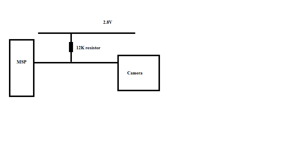
I have attached both the datasheet end the pictures of the module.

  • What do you want to do with it?
    The MSP series has netierh the required throughput nor the ram to handle and process VGA images. You can sue the MSP to control the camera function (e.g. generate control signals based on RS232 commands for changing the focus or move the camera or such), but even the biggest MSPs are by far too small to work on the camera images itself.
    Except if you're just taking snapshots, read them slowly and do some claculations on the stream such as average brighness to auto-adjust the brighness setting. But looking at the image as a whole, or in realtime, is impossible.

    lovelesh said:
    o is there a way where I can make sure that the camera is focused properly and getting the right image?

    Like calculating the average brigness of a still image (given enough time), it could be possible to calculate the maximum contrast by looking jsut at adjacent pixels or lines, as they stream in. This could be takesn as indicator for a wrong focus (= no sharp edges between pixels), but of course it depends on the image. It's even possible to do sort of an auto-focus, but it will be slow and not realtime.

  • Hi Jens,

               Sorry for the late reply. I had no internet connection for 5 days.

      I am working on "face recognition", which uses eigenface algorithm to recognise persons. So a part of it is to read images that are sent by the camera. So to be familiar with the camera I am planning to interface the camera using I2C and send the data serially to MATLAB where I can view the data and process it.

    The main problem with the camera is that it doesn't have analog output, so I cant view what the camera is capturing. I am using Launchpad

      Is there a way where I can send data through the USB? Are there any programs available?

    I have heard that SERIAL command in MATLAB directly reads data from the specified ports.

  • Hi lovelesh,

    you can not read the image using the I2C link. The I2C is only to set and read some control registers in the camera.

    You need to read the data on the parallel databus of the camera module - each time the pixelclock is changing, a new byte is at this bus and you need to store this byte into RAM, increment address and store the next byte... needs several Megabytes of RAM. MSP430 with max 16kBytes is the wrong controller to read the whole image. However you can read single lines of the picture and store this in the MSP-RAM this should be possible using DMA. And you can send this single lines serially to a PC.  it is not impossible at all, but there are much better solutions ;-)

    Leo.

  • Hi Leonix,

                     I cant change my hardware now, I have already bought the camera and the Launchpad.

    Can u give me some other way of interfacing the camera?

    Can I use a serial data flash to store the data and then send it to MATLAB.

    Can you give me some sites where I can get info about interfacing the camera?

  • lovelesh said:
    I cant change my hardware now, I have already bought the camera and the Launchpad.

    Then you have a camera and a Launchpad, but no project.

    As Leonix stated, the MSP processors (and especially the LaunchPad processors with their max. 512 bytes ram and the limited I/O ports) are by no way suited to deal with realtime image data. IIRC, data is typically coming out with 6MHz. So if you get it connected, the memroy would fill the ram at a speed that requires 100% of the fastest possible clock, leaving zero processing power for doign anything with the image. Just moving from I/O port to ram will take all an MSP can give. Not to ention that the available 1k of ram will be filled in 1/6000 second. With nobody able to process or forward it.

    YOu can sue the LaunchPad/MSP to control the camera, but not to do anything with its image output. Yoiu can make a controller for brightness/focus, fo rcontrollign a tilt/rotation motor etc. But you cannot do anything with the image data itself. Period.

  • Hi Jens,

                  Is there any way to view the images by using MSP?

    We have a DSK 6713 at my college. It's a spectrum digital board but the problem is that it doesnt have usable I/O pins. So it becomes very difficult to interface the camera with the DSK. So I decided to check the camera output using the MSP.

    So can u suggest any alternate ways of interfacing the camera with the MSP or the DSK? I prefer both of them.

    4237.dsk6713_TechRef.pdf

  • Let me answer with a question:

    If I have a well that produces 10 gallons of water per second and a 1-gallon bottle to carry it form the well to a reservoir, and I cannot directly connect the well with the reservoir, how can I bring all the water form the well to the reservoir?
    SImple answer: you need to move faster than the light. Or use a pipe instead of the bottle. The MSP is this bottle. Suited for many othe rthings, but not by any means sufficient for processing image data from a camera. No matter how hard you wish.

    There might be dedicated chips available that take input data and spill it out again as an SPI data stream. There are processors which are much faster than the MSP and can read data form the camera and have much time left to even process it before forwarding. However, none of them will be as small and power-efficient as the MSP. Use the tool that fits best. Take a small if it' ssufficient, take a big if needed. Here you need a big one.

  • Thanks jens,

                         You clarified my doubt that msp is not enough for the camera. Now as i have the camera and i wanna start interfacing it with the DSK6713 or DSK6416. Both of these kits are in our college. Also they were purchased in 2006. These kits are not available to us for the whole day.

    So can u suggest of some easy to get uC so that i can start interfacing at home? my ultimate aim is to use the DSK as uC wont be enough for my 'face recognition system'.

    Plz send me ur suggestions.

  • This is an image processing task. Image processing is very data & computation intensive - so you need a high-power processor with lots of memory.

    You are not looking at cheap microcontrollers!

    A Beagleboard or similar is probably appropriate...

    http://beagleboard.org/


  • Hi Andy,

                 I came to know that MSP is not suitable for image processing application. So i m thinking of using DSP 6713 or Piccolo series processors. As DSP processors are available in my college and I have budget constraints. So I thinking towards piccolo as its low cost. We cant buy the beagle board as its costly and much of its hardware will not be used.

    Are piccolo capable enough for image processing application?

    Should i stick to DSP 6713?

  • Is this the same project: http://e2e.ti.com/support/microcontrollers/msp43016-bit_ultra-low_power_mcus/f/166/t/154071.aspx ?


    lovelesh said:
    I have budget constraints

    Did you not discuss with your tutors whether your proposed project was likely to be achievable within those constraints?

    The size of the budget should be a clue to the expected level of complexity of the project...!

  • Hi Andy,

                 this is the same project and  I and mehul are working together. He is working on DSP and i am working on msp.

  • Hi Andy,

                 You said that MSP is pretty small device to interface camera. I want to get familiar with the I2C.

    So can i use the msp to communicate with the camera. I donot want the whole image only some part of it. May be 10 bytes are enough for me while learning

  • Hi Leonix,

                    I want to write a program that reads only few bytes of the camera. My real goal is to implement this onto DSK6713.

    Can u give more information about initializing the camera and receiving the bytes? But for now i just want to use the MSP for trial purpose. A few memory spaces of MSP are enough for me right now.

    Also can u give more information on DMA usage?

    Now I am not planning to send the data to PC, but I will save the memory in the .dat file and check in MATLAB. We are doing the same in DSK. We take the image from a DSC and convert it into .dat file using MATLAB. Then we load the memory in DSK and run the code. It works fine.

    I am planning to do the same but on a smaller scale. 

  • Hi Jens,

                  The Toshiba camera works on max 2.8V, while the MSP works on 3.3V. So can i connect SDA and SCL lines directly? Similarly can the ports be connectly directly to MSP?

  • lovelesh said:
    The Toshiba camera works on max 2.8V, while the MSP works on 3.3V.

    Why don't you operate the MSP with 2.8V too?

    However, I2C is using an open.collector bus.
    So the bus is held high by pullup resistors and only driven low by the peers. The peers never drive the lines high by themselves.

    If the pullups go to 2.8V, this will be considered high by both, the camera and the 3.3V driven MSP.

    For the ports, things are different. The ports are driven high and low, sothe MSP will output its 3.3V to the port pins.

    However, a trick can be used here too: Apply external pullup resistors to the output lines to 2.8V. Then switch the port pin between low output (which pulls the line low) and input (which releases the line which in turn is pulled high to 2.8V by the pullup resistor).

    Signals coming from the camera to the MSP do not need any attention. As long asn teh camera is providing a high-level signal > 2.2V (for the exact vlaue see the MSP datasheet) it is considered heigh. it does not need to be 3.3V.

  • Hi Jens,

                  Can u show me a diagram to understand better. Right now i am connecting 12K resistors between VSS and SDA/ SCL. Am i doing right?

  • lovelesh said:
    Can u show me a diagram to understand better.

    Hmmm, looks like I mixed-up two threads in my last post (happens if your typing is interrupted frequently by your job). Sorry for that confusion.
    Of course the port switching is not required when using a hardware I2C module such as the USCI or USI. It was meant for a software SPI in a different thread, which was done by GPIO pins.

    lovelesh said:
    Right now i am connecting 12K resistors between VSS and SDA/ SCL.

    If the camera runs on 2.8V, then you should put the pullups to 2.8V. This is still high enough to be recognized by the MSP as high level, and won't rise the bus voltage above the camera supply.

  • Hi Jens,

                 I did as you told. I connected the SDA/SCL pins to 2.8V. I also made P1.6 high and connected it to pull up resistors to 2.8V.

    But when the BIT is 0, voltage remains 0. But when the BIT is 1, voltage jumps to 3.5V.

    Kindly help

    Now there is problem: when i connect a common ground the voltage climbs to 3.5V. But when no common ground is connected the voltage slips down to 2.8V

  • lovelesh said:
    I connected the SDA/SCL pins to 2.8V. I also made P1.6 high and connected it to pull up resistors to 2.8V.
    But when the BIT is 0, voltage remains 0. But when the BIT is 1, voltage jumps to 3.5V.

    There is a difference between the USCI (or USI) I2C hardware and the normal port pins. When the USCI operates in I2C mode, it pulls the line low or releases it. It never pulls the line high. So the line is either 0V (pulled low) or 2.8V (pulled high by pullup).
    When using a normal I/O for a software I2C, you must not have the pin set to high output. That's what I was describing above (so it seems to for for this thread too, even if meant for another one): you switch the port pin between low output for low and high-impedance input without internal pullups for high.
    You do not toggle the PxOUT.y bit, but rather the PxDIR.y bit. With reversed logic:
    Leave P1OUT.6 to zero (low output).
    If you want a low output, set P1DIR |=BIT6. To release the line and let it pulled up by the pullup, set P1DIR &=~BIT6. Now it is high-impedance input (you can even read what the slave is telling you on P1IN), and only pulled up by the external pullups to 2.8V (if the slave doesn't pull it down).

    If using USI or USCI for I2C, it does (more or less) exactly that.

    lovelesh said:
    Now there is problem: when i connect a common ground the voltage climbs to 3.5V. But when no common ground is connected the voltage slips down to 2.8V

    If you do not connect the GNDs, you'll measure 0,.7V between the two GNDs. Making up for the 'missing' difference between 2,.8V and 3.5V.
    However, without GNDs connected, it won't work at all, as no curent will flow (the backpath is missing) and therefore no side will detect any voltage change by the other sides signal. That's the "very special relativity theory" about metering and voltage/current detection (not related to Einstein)

**Attention** This is a public forum