This thread has been locked.
If you have a related question, please click the "Ask a related question" button in the top right corner. The newly created question will be automatically linked to this question.
Hello,
Recently, I designed a custom PCB with the MSP430FR5739. I purchased a FRAM experimenter board to program it, but so far I haven't had any success. The error I get in CCS is:
Error connecting to the target:
Could not find device (or device not supported)
I am able to program the default MSP430FR5739 on the experimenter board without trouble, however the MSP430FR5739 onboard my PCB always produces the above error. I have four lines connected from the FRAM experimenter board to uC on my PCB:
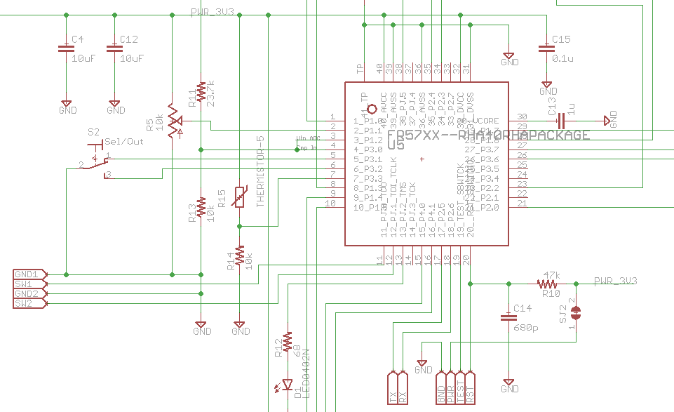
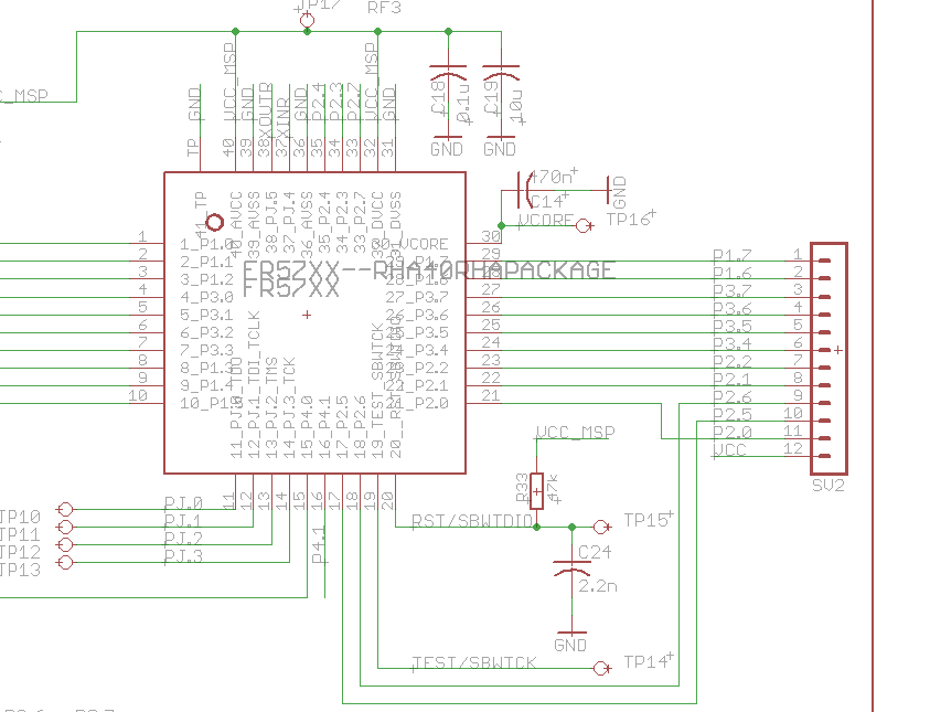
I've verified that the power going into the microcontroller looks good: 3.6V on VCC and 1.5V on VCore. Likewise, the only differences I can see between my schematic, and experimenter board are slightly different capacitance values on RST and VCore. I have a 680p capacitor instead of 2.2n on RST, and a 1u capacitor on Vcore instead of 470n on the experimenter board. Otherwise, as far as I can tell they're identical.
My Board:
Fram Experimenter Board:
I've tried using two different MSP430FR5937s on my PCB, but I encountered the same error each time. Any help would be appreciated.
Daniel Kuo said:... the only differences I can see between my schematic, and experimenter board are slightly different capacitance values on RST and VCore. I have a 680p capacitor instead of 2.2n on RST, ...
Take out that 680p cap. on RST.
Thanks for the suggestion. However, I still get the same error after removing the capacitor. Only the 47k pull up resistor remains.
Not long ago I used an FR Launchpad to program an FR5738 (PW) which was mounted on a bare(!) board -- no Vcore cap, no RST conditioning, just the chip.
One thing I did differently from your photo was that I removed the VCC jumper on J3, and fed my board with the Emulator-side VCC pin. (GND can be taken from anywhere on the board.) I wonder if you're getting interference from something on the Target side of the board due to powering that half up.
Bruce,
I tried programming the MSP on a bare board, but no luck there either. Likewise, moving the jumper to the emulator side VCC gave no results.
Not very long. About 6 - 8 inches. I'm going to try observing the TEST and RST lines this evening on an oscilloscope to see if anything looks off.
TEST is actually a clock signal and RST is actually bi-directional data (that is why you should not have your 680pF cap. on this line). The waveforms on these two lines are very complex. But you can compare what you see when they are talking to your own Board (not working) vs. when they are taking to the lower part of your LaunchPad (working). Watch for (a) voltage levels -- there should be a high level near 3.6V, a low level near 0V and possibly a "floating" level when neither side is driving the bi-directional data line RST, (b) rise and fall time, and (c) timing relation between the clock TEST and the bidirectional data line RST.
Good luck and please tell us your findings.
So I had a chance to look at the waveforms on the oscilloscope, and I can see something weird going on. I set the scope trigger to fire on the first falling edge of RST, so the signal captured here is the first signal sent when starting the download. Probe 1 is connected to TST, and Probe 2 to RST. (Apologies for the phone-camera oscilloscope shots. I'm using an old scope that can't save waveforms)
Oscilloscope capture for the functional on-board FRAM chip:
Oscilloscope capture for non-functional FRAM IC soldered to my PCB:
First off, I can see the effect of the 2.2n capacitor on the RST line on the on-board FRAM. The signal rise/fall is slower, compared to the crisp edges of the PCB FRAM which has no capacitance on RST. However, the on-board FRAM is working fine with the 2.2n cap, so that isn't an issue here.
What's interesting though is that I can also see some odd signal blips appearing on RST for the PCB FRAM. They have slow rise times, contrasting with the sharp edges when the line is being actively driven. I believe these blips must occur when the bus is tri-stated, and the pullup resistor and parasitic capacitance slowly pulls the line high. These false signals blips must be what's confusing the programmer.
What's interesting is that these blips seem to appear on the functional on-board FRAM RST line as well, but their magnitude is much much smaller. I've highlighted in green and orange the signal blips I'm talking about in the image below.
I'm wondering if the 2.2n capacitor on the line holds the signal levels steady while the bus is tri-stated, and as a result there is a minimum capacitance requirement I'm not meeting. Likewise, I know there is a maximum capacitance you can put on RST, so I'm thinking 2.2n must the be perfect in-between value. I don't have any 2.2n caps on hand, but I'll see if I can parallel a few together and test this theory out.
Yep, looks like the 2.2n capacitor fixed it. The 680p I had earlier wasn't enough, nor was the 1.5n I tried later. So it looks like the acceptable capacitance range on the RST line is fairly narrow.
With the 2.2n though I am finally able to program the device properly. Thanks for the help.
**Attention** This is a public forum