This thread has been locked.

If you have a related question, please click the "Ask a related question" button in the top right corner. The newly created question will be automatically linked to this question.

Difficulty trying to program my custom PCB(MSP430FR5739) with the MSP-EXP430FR5739 experimental board

Other Parts Discussed in Thread: MSP430FR5739, MSP-EXP430FR5739, MSP-TS430RHA40A, MSP430G2553

Hi All,

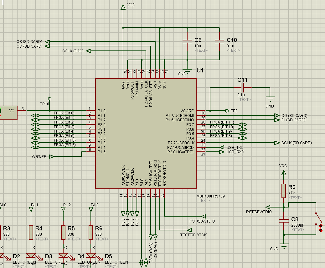
I have designed a custom PCB with the MSP430FR5739 as the core microcontroller. My design is with respect to the design specifications on the MSP-EXP430FR5739 schematic, and I have been trying to program my custom PCB with the emulator of the MSP-EXP430FR5739 experiential board, but everytime I try to load a simple program like switching on 2 led's I get an error from the code composer studio such as this:

[ MSP430: Error connecting to the target: Could not find device (or device not supported) ]

I am able to program the experimental board (MSP-EXP430FR5739) on it's own, meaning that works well, but I can't use that emulator to program my custom PCB.

I have connected the SBW (Spy-Bi-Wire) configuration from the experimental board emulator (TEST, RST, GND & Vcc) to the custom PCB (MSP430FR5739) corresponding pins, yet I still encounter the same error message on my CCSv6.1.1.

I've verified that the power going into the custom PCB is: 3.56V on Vcc and 1.48V on VCore. Likewise, the only differences I can see between my schematic for my custom PCB, and experimenter board (MSP-EXP430FR5739) are slightly different capacitance values on VCore. I have a  0.1u capacitor on VCore instead of 470n on the experimenter board. Otherwise, as far as I can tell the schematics are the same.

Could someone assist me regarding this? is there something that I'm missing on this matter?

Regards,

Lubabalo

  • Hi Lubabalo,

    As stated in the device datasheet a Vcore capacitance of 470 nF is required, not just a recommendation. You must also make sure that the capacitor ratio of VCC to VCORE is at least 10:1. The recommended DVcc & AVcc decoupling capacitance is 10 uF + 100 nF at each pin. Please also ensure that the 47 kOhm pull-up resistor and 10 nF pull-down capacitor have been correctly installed on the RST line. And I know this comes standard on the MSP-EXP430FR5739 but TI does not recommend that a Vcc of 3.6 V be used for MSP430 devices as this is the maximum allowable Vcc and anything above that is considered out of spec.

    Regards,
    Ryan
  • Hi Lubabalo,

    It is better if you can provide the custom circuit. There must be something different even you think they are the same.

    3.56V is really to high for MSP430. FYI, I usually use 3V. Please follow Ryan's suggestion to see if the problem can be solved.
  • Hi Ryan,

    Thanks, for the advice I might have overlooked the capacitance value of VCore, I'll change it and get back to you, The decoupling capacitance values for  DVcc & AVcc are kept as 10uF + 100nF, on RST line I've used a 47kOhm resistor as the pull up resistor and a 2.2nF pull-down capacitor.

    My question to you is, should I change the pull-down capacitor to 10nF as you have stated, because I cannot see it specified on the datasheet?! I will also find a 3V power supply in my workshop and apply the recommendations you have mention, and get back to you with my results.

    Please also find attached the screenshot of my schematic diagram for further help.

    Thanks,

    Lubabalo

  • Hi rcfocus,

    Please look at my reply to Ryan, you'll also find my schematic attached.

    Thanks,
    Lubabalo
  • Hello Lubabalo,

    2.2 nF is fine and is even what's recommended on the MSP-TS430RHA40A target board. The AVcc & DVcc pins are recommended to each have 10 uF + 100 nF, not a shared capacitance, although this is less critical than the Vcore capacitance and operating voltage level. Please keep me updated after making the changes.

    Regards,
    Ryan
  • Hi Lubabalo,

    Please also post a clip picture of debugger port circuit. I want to check the debugger connection.

  • Hi Ryan,

    For the past few days, I've changed the VCore cap, and used a 3.21V DC supply, but yet still no change from the results that I previously had. Is there maybe a BootLoader program that you're are suppose to load on the micro before you use it or is there an internal safety fuse which might be blown?, because I really can't think of what could be wrong with the msp430.

    Regards,

    Lubabalo

  • Hi Lubabalo,

    The error you are receiving (could not find device) has nothing to do with the BootLoader or the JTAG security fuse, if those were the case then the error would indicate as such. The target device is a blank MSP430FR5739? Reconfirm that your RST passive components are correct and that the pushbutton used is normally open (RST line should be high during inactivity due to the pull-up resistor). Can you provide a picture of how you connect the MSP-EXP430FR5739 emulator to your target board? Vcc, GND, RST, and TEST should be connected. The difference in Vcc level between the emulator (3.6 V) and target board (3.2 V) might be of concern.

    Regards,
    Ryan
  • Hi Ryan,

    The MSP430FR5739 on my target board is blank as it is still new and hasn't been used until now, RST passive components are correct, as I have used a normally open pushbutton, and I am reading a high during inactivity.

    Above is the picture of how, I have connected the the emulator of the MSP-EXP430FR5739 to my target board. 

    Thanks,

    Lubabalo

  • Ryan Brown1 said:
    Hi Lubabalo,

    As stated in the device datasheet a Vcore capacitance of 470 nF is required, not just a recommendation. You must also make sure that the capacitor ratio of VCC to VCORE is at least 10:1. The recommended DVcc & AVcc decoupling capacitance is 10 uF + 100 nF at each pin. Please also ensure that the 47 kOhm pull-up resistor and 10 nF pull-down capacitor have been correctly installed on the RST line. And I know this comes standard on the MSP-EXP430FR5739 but TI does not recommend that a Vcc of 3.6 V be used for MSP430 devices as this is the maximum allowable Vcc and anything above that is considered out of spec.

    Regards,
    Ryan

    Don't know about 0.1 uF on VCore pin, but there is no problem with my 5xx boards where VCore cap is 220 nF. There is no more than 10 uF of total DVCC / AVCC decoupling on my boards. 5xx devices have internal pull-up on RST line and external one is not needed. External combination (47 kOhm and I guess 1 nF, not 10 nF) only disturb SBW. MSP430 working just fine on 3.6V.

    If I remember right some LP FR boards have old silicon that is not supported any more, and maybe here problem is related to on / off board target device chip silicon difference, and LP is working fine with on board chip, but not working with custom board.

    And why Error connecting to the target: Could not find device (or device not supported) can't be separated in 2 errors. Than it will be completely clear if there is no target, or device is present but not supported.

    Lubabalo Mpolongwana said:

    Is there maybe a BootLoader program that you're are suppose to load on the micro before you use it or is there an internal safety fuse which might be blown?

    Your LP support G2 devices (for example MSP430G2553), so you can try to program you FR board by G2 LP based BSL (slaa535 LaunchPad-Based MSP430 UART BSL Interface). Don't think that on your target board fuse is blown, but it can be unblown by BSL.

    http://forum.43oh.com/topic/2972-sbw-msp430f550x-based-programmer/?p=43889

  • Hey Lubabalo,

    The image you provided doesn't help me see the connections between the two boards. I need to be able to follow the jumper wires completely. But based on the way your JTAG header on the target board is populated I believe that the connections are incorrect. Please refer to Figure 2-3 of the MSP430 Hardware Tools User's Guide (SLAU278): www.ti.com/.../slau278w.pdf

    Regards,
    Ryan
  • Hi Ryan,

    The way the JTAG header is populated on the target board looks a bit different to the one from your pdf link, but all the pins(RST, TEST, Vcc, GND) are there and they are connected to the corresponding pins on the MSP-EXP430FR5739, so clearly that was not the problem.

    I ended up getting another microcontroller to replace the one I had on my custom board and it simply programmed first time. Thanks, for your help though as I have learnt alot from your recommendations and discussions.

    Regards,
    Lubabalo

**Attention** This is a public forum