This thread has been locked.
If you have a related question, please click the "Ask a related question" button in the top right corner. The newly created question will be automatically linked to this question.
Hi All,
Have been working with a board I designed with the G2402. All was going well for a couple of weeks until this morning. Made some changes to my code - primarily added the following few lines to the source in main() -
P1SEL = 0x00;
P2SEL = 0x00;
P1SEL2 = 0x00;
P2SEL2 = 0x00;
P1REN = 0x00;
P2REN = 0x00;
P1DIR = 0xFF;
P2DIR = 0xFF;
P1OUT = 0x00;
P2OUT = 0x00;
Rebuilt project and downloaded using FET430UIF (JTAG 4 wire mode). Download was successful. Tried to run the code with some breakpoints; the debug session died on me (has never done this before; has been always very reliable in the past). I tried to restart a debug session with F11 and now I have started getting an error "MSP430: Error connecting to the target: Unknown device". The code before I added the above lines was -
P1REN = 0xFF;
P2REN = 0xFF;
P1DIR = 0xFF;
P2DIR = 0xFF;
I tried another board. The code downloads the first time; then the debug session dies; and after that the FET cannot communicate with my boards anymore. Have already destroyed two boards, it seems.
I have also tried two different FET430UIF modules. Same problem.
I would have thought that the FET would always be able to reset the G2402 over the JTAG. But somehow adding those few lines (P1SEL, P2SEL, P1SEL2, P2SEL2, and changing P1REN and P2REN to 0x00) kills the G2402 so that even the FET cannot reset it again.
I downloaded the elprotronic software and tried using it - it fails too. See attached screenshot.
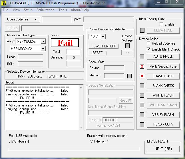
Did the two lines that disable the pull up resistors kill the G2402? I have looked at all the I/O lines on the schematics and none of them should damage the G2402 just because the pull ups get disabled on the chip. Can someone give me some ideas to try to see if I can recover these two boards without having to replace the G2402? Thanks in advance.
Hi Ketan,
One thing worth checking, P2.6 and P2.7 are defaulted to the "alternate" function of XIN and XOUT (P2SEL.6/.7 = 1, P2SEL2.6/.7 = 0). You could try leaving out the initializations for P2.6 and P2.7 and see if that makes a difference.
Also, if you are setting the direction bit to 1 (output mode), there is no need to use the internal pull resistors (setting REN bit to 1), as the 430 is already active driving the IO line.
Finally, are you sure the mentioned lines are the root cause of your problem? If you create a test project that just includes those lines of code, do you still see the same failure?
One of the unfortunate things about debugging issues that brick devices, you typically end up bricking several during the testing process. I recommend using a G2 LaunchPad for testing this, as it is really easy to pop out bricked devices and putting in new ones for testing.
Mike
Mike, Luis - Thanks for the replies.
To answer Mike - Am certain that those are the only lines of code. Had added some other code; but its more application related code that processes data. The only other change was that P2.6 which was previously unconnected on the board was now connected to another part (GDO0 output on a TI CC1101). So I added some code to use P2.6 as an input and then enabled the interrupt on P2.6 rising edge. The actual code in my source file is -
#define RF_RECEIVE (char) 0x40 //P2.6 GDO0 input
P2SEL &= ~RF_RECEIVE;
P2SEL2 &= ~RF_RECEIVE;
P2REN &= ~RF_RECEIVE;
P2DIR &= ~RF_RECEIVE;
P2IES &= ~RF_RECEIVE; //rising edge only
P2IFG &= ~RF_RECEIVE;
P2IE |= RF_RECEIVE;
And then I added some code in the ISR for Port2 that retreives a frame from the CC1101.
Previously when everything was working, I was polling the GDO0 state in the status register to detect when a frame was available. And it was all working fine. As a matter of fact, the interrupt was also working fine because at first I had the interrupt coming in a falling edge (had P2IES |= RF_RECEIVE). So I saw the interrupt when debugging, realized the error, ended the debug session, changed the P2IES setting for P2.6 to zero (instead of one) AND added the other code (mentioned in my first post) around the beginning of the main() function. Those were the only changes made. And then a rebuild and download. And now I have two boards that don't respond to the FET tool.
Mike - Are you saying that changing P2.6 from XIN functionality to GPIO function could cause the problem I am seeing? You have suggested I go back to not using P2.6 (and leaving it as before - XIN - default power on state). But to test this, I will have to risk a third board. And it does not help me if it works because I do need to use P2.6 in the final product.
If I buy the G2 Launchpad that you recommend, will I be able to connect the rest of the peripherals I need to test (such as the CC1101)?
Luis - I have one board that I can use with SBW. But I am afraid I will end up losing that board too. Are you suggesting I download the same code (that bricked my other two boards that are using JTAG 4 wire) to the board that is configured to use SBW and see what happens?
Awaiting your suggestions.
**Attention** This is a public forum