This thread has been locked.

If you have a related question, please click the "Ask a related question" button in the top right corner. The newly created question will be automatically linked to this question.

MSP430F2274 SPI Shift Issues

I'm trying to operate SPI in the slave mode, and I can't seem to get reliable output from the MSP430 to the master. The master device (an FPGA) sends indices 0x00-0x26, and then 0xFF to indicate the end of transfer. There is a pause equal to the transfer time of one byte between each index. The SPI clock is very slow, ~40KHz.

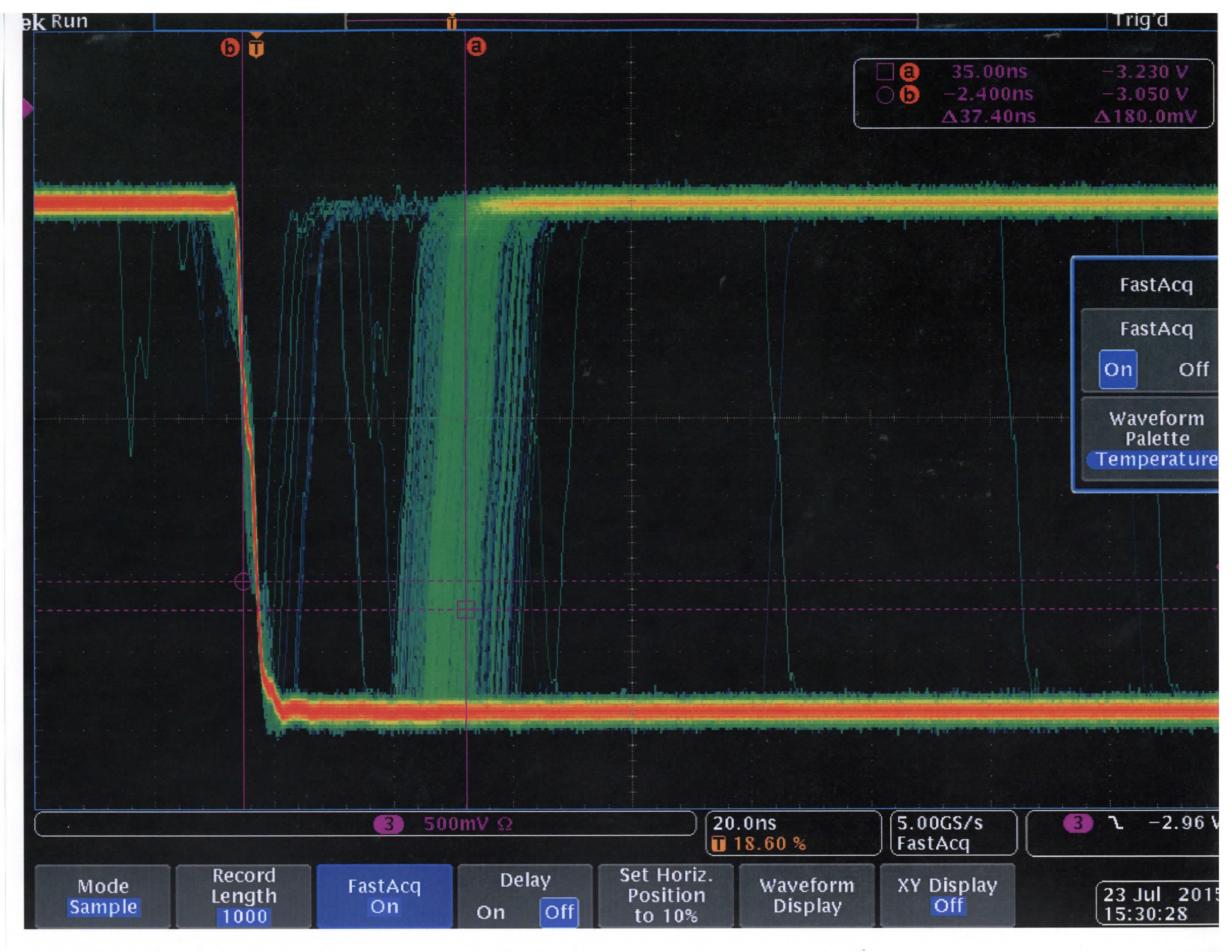
I wasn't getting reliable data from the MSP430, so I started removing things from the program, thinking that I had a pointer arithmetic error somewhere that was stomping on TXBUF and/or RXBUF. However, now I've got almost nothing in the program except disable the watchdog, set the clock, initialize my GPIO, initialize the SPI, and transmit a fixed byte, and I can't get reliable operation. The byte I'm transmitting (0xA5) looks like it gets shifted. I'm monitoring on an oscilloscope and at first I do indeed get 0xA5, but eventually I start getting 0x4B, 0x2D, 0x5A, 0xB4, 0x96, 0x69, etc.

When I pause in the debugger, I still see 0xA5 in UCA0TXBUF, despite the oscilloscope showing that's not what's transmitted. UCA0RXBUF is also corrupted.

I'm aware of the USCI40 error, and I'm not using UCCKPH. I've also tried the solution there to no avail. Any ideas? Is there an integrity test to run on the MSP430 to make sure the hardware is working properly?

Spi init:

UCACTL1 |= UCSWRST;
UCACTL0 = UCCKPL + UCMSB + UCMODE_2 + UCSYNC;
// P3SEL for my I/O goes here
UCACTL1 &= ~UCSWRST;
IE2 = UCA0RXIE + UCA0TXIE; // I have tried just UCA0RXIE, and no interrupts as well
UCA0TXBUF = 0xA5;

Rx ISR

if (IFG2 & UCA0TXIFG) {
    cSpiTxIfg++;
    UCA0TXBUF = 0xA5;
    // Also tried UCA0TXBUF = UCA0TXBUF, UCA0TXBUF = UCA0RXBUF
}

:

if (IFG2 & UCA0RXIFG) {
    cS

  • if (IFG2 & UCA0TXIFG) {
        cSpiTxIfg++;
        UCA0TXBUF = 0xA5;
        // Also tried UCA0TXBUF = UCA0TXBUF, UCA0TXBUF = UCA0RXBUF
    }

    The last bit of code (Tx ISR) was supposed to read...

  • Hi Jonathan,
    Can you send me the rest of your code by chance?

    Also, how are you setting up your scope?
  • src.zipI'm not sure how useful this attached code will be, it's not the paired down version I've been using. It's a semi-recent version, but it should give you an idea how the functions are split up. Obviously this doesn't have anything disabled. I've disabled pretty much everything in main.c except the SPI and changed both spi.c and i2c.c as detailed in my previous posts (and in various other configurations trying to get something to work). I might also be missing some of the other counters I pasted in the previous code. Let me know if you have questions.

    The scope samples the entire SPI transaction with sck, csn, mosi, and miso on the fast analog separate inputs using the SPI bus function, which is set to sample on sck rising edge with csn low. Thresholds are about ~1.5V.

  • Can you post an image showing an oscilloscope capture of the problem?

    Regarding your question about internal testing, you can either connect the MOSI and MISO pins together externally, or set the UCLISTEN bit to enable internal loopback.

    Also, I suggest trying UCMODE_0, just to eliminate the possibility that STE timing is somehow causing problems with the transmission.

  • Yes, but unfortunately not until Monday.

    In the mean-time, is there any self-test I can run on the microcontroller to verify functionality?
  • I've spent some time examining your code, and everything I can think of seems to be in order. I'd like to try to reproduce the problem , but unfortunately I wont be able to get the board I need until Monday.

    In the mean time, if you have the chance to send me the code you are using to isolate the issue, that would really help me to not do duplicate work and to make sure we are working from the same set.

    If you can tell me how you tried to implement the Errata fix (especially if it was reloading the buffer in a function rather than the ISR) , I can rule that out as well.

    I'm assuming that your clock signal is still coming from your FPGA?
  • It will take some time, but I will get you the modified version as soon as I can Monday.

    The errata fix shouldn't apply since clock phase select is 0, but I was willing to try just about anything. I tried reloaded the Tx buffer in both ISRs (not a separate function). I also tried reinitializing the SPI before that (I created an inline void Spi_hwInit() with steps 1-5 from Spi_init() from Spi.c). Tried doing that in the Rx ISR as well.

    Yes, the FPGA is the master SPI device and generates sck, csn, and mosi. The MSP430 generates miso.

    I'm worried that somehow we damaged the MSP430 (although everything seems to work except SPI). Is there an integrity/self-test I can run on the MSP430?
  • 0871.src.zipI have attached what should be the latest modifications I am running.

    I will try and get some time with the unit today to capture the SPI traffic on the scope as well.

  • The zip file contains several oscilloscope shots (sorry for the quality). 1/yellow is sck, 2/blue is csn, 3/red is mosi (fpga to uC), 4/green is miso (uC to fpga). In these tests I set the TXBUF = 0xA5 in the init routine, and used the tx IRQ to set TXBUF = 0xA5 again. You can see in some of the transfers that the uC will simply change the transmitted byte. If I pause the debugger after the transmit data is no longer valid, TXBUF still shows 0xA5, and RXBUF is corrupted (should be 0-26 or so, or FF, and is not).

    scans.zip

  • Jonathan, would you mind converting those images from PDF to an image format (JPG/GIF/PNG/BMP)? Thanks.
  • Ok, there's something odd going on with the chip select signal there. Your FPGA is outputting while CSN is not active (repeating the same byte as when CSN is active). The MSP430 output doesn't appear to be synchronised to the edges of CSN either (there are some runt pulses at the CSN transitions).

    What happens if you keep CSN active all the way through the transfer? Perhaps try that with the MSP430 set to 3-wire mode too.

    EDIT: Yes, I think this problem is due to UCMODE_2. The USCI STE functionality doesn't synchronise to a byte boundary or reset the shift registers on an STE edge. Jens-Michael Gross has noted this issue a few times previously, for example: https://e2e.ti.com/support/microcontrollers/msp430/f/166/p/251036/880824#880824.

    EDIT2: In fact, I'm not convinced the MSP430 is handling the chip select signal at all, it should be switching MISO to high impedance when CSN is high, but it continues to output (as does the FPGA.)

  • The FPGA talks to two MSP430 devices on the SPI bus. The FPGA ping-pongs between the two devices to give enough time to load initially. While CSN is high the FPGA is talking to the other MSP430 on the bus (which has the same issue).
  • The article you link shows PxSEL pins as the culprit. My two MSP430s are talking at the appropriate time, but they're not outputting the appropriate data.

    I cannot change to 3-wire mode as there are unidirectional buffers involved.

    I can change the FPGA so that it doesn't ping pong between the two devices, but I won't be able to do that today (hooray for meeting Mondays).
  • Jonathan Miller said:
    The article you link shows PxSEL pins as the culprit. My two MSP430s are talking at the appropriate time, but they're not outputting the appropriate data.

    I wasn't referencing the original post in that thread so much as JMG's replies. He points out that the STE signal does nothing to force the USCI to realign itself to the start of a byte. In other words: if the USCI happens to output two bits before being silenced by STE, when STE goes active again it will resume with the following six bits of that byte and the first two bits of the next. From that point on the USCI output will be shifted by two bits, unless the program resets it.

    Jonathan Miller said:
    The FPGA talks to two MSP430 devices on the SPI bus. The FPGA ping-pongs between the two devices to give enough time to load initially. While CSN is high the FPGA is talking to the other MSP430 on the bus (which has the same issue).

    Aha, now I understand those scope captures! Simplifying the test setup to just use one MSP430 and the FPGA will definitely help clarify what's going wrong.

    I think you're already doing the right thing with the timing of CSN relative to the clock. CSN drops before a falling edge of the clock, so the clock edge triggers the output of the first bit. CSN goes high again after the rising clock edge which triggers sampling of the eighth bit, preventing the USCI from starting to transmit the first bit of the next byte.

    It might also help to get captures of the bus state during setup, as it's possible that USCI is being pushed out of step at that point. Transitions on the clock or CSN lines between the USCI being taken out of reset and the start of transmission could knock it out of sync.

  • Robert,

    What interests me is at one point the output is B4, B5, 69. 

    Lined up:

    10110100

    10110101 <-- Only a single bit has changed or shifted. Which destroys the A5 pattern.

    01101001

    I'd be curious to hear your thoughts.

  • Cameron LaFollette said:
    What interests me is at one point the output is B4, B5, 69. 

    Yes, that part has me perplexed too. Hopefully it'll become clearer with some scope captures where CSN stays active throughout.

  • Robert Cowsill said:

    I wasn't referencing the original post in that thread so much as JMG's replies. He points out that the STE signal does nothing to force the USCI to realign itself to the start of a byte. In other words: if the USCI happens to output two bits before being silenced by STE, when STE goes active again it will resume with the following six bits of that byte and the first two bits of the next. From that point on the USCI output will be shifted by two bits, unless the program resets it.

    Okay. In one of the myriad program iterations I ran Spi_hwInit() (Spi.c), which should reset the SPI state, if I understand correctly. Should doing that at the end of each Rx transfer along with UCATXBUF=UCATXBUF in the Tx ISR be sufficient to cover all errata/reset the SPI for each transfer? Or should I run Spi_hwInit() in the Tx ISR as well?

    Robert Cowsill said:

    Aha, now I understand those scope captures! Simplifying the test setup to just use one MSP430 and the FPGA will definitely help clarify what's going wrong.

    Yes, sorry, I should have explained the transfers more completely. That's pretty much everything. The transfers occur every 100ms.

  • Robert Cowsill said:
    Cameron LaFollette
    What interests me is at one point the output is B4, B5, 69. 

    Yes, that part has me perplexed too. Hopefully it'll become clearer with some scope captures where CSN stays active throughout.

    The bit progression Cameron posted above looks like either a combinatorial glitch or a timing issue to me.

  • I still have issues even with CSN low for the entire transfer. However, the data appears more stable. Note that it is not correct, but I couldn't capture any successive bit changes within a SPI transfer as I was able to do before.

    Again, if I pause the debugger and look at TXBUF it shows 0xA5 despite something different on the scope, and RXBUF is corrupted (does not contain 00-26, FF).20150721.zip

  • Robert Cowsill said:
    It might also help to get captures of the bus state during setup, as it's possible that USCI is being pushed out of step at that point. Transitions on the clock or CSN lines between the USCI being taken out of reset and the start of transmission could knock it out of sync.

    Sorry, meant to respond to this earlier. You are talking about startup/power-on right? The FPGA powers up before the MSP430, so the SPI inputs to the MSP430 should always be stable before the MSP430 powers on.
  • Jonathan Miller said:
    Should doing that at the end of each Rx transfer along with UCATXBUF=UCATXBUF in the Tx ISR be sufficient to cover all errata/reset the SPI for each transfer?

    That causes absolute chaos, which is interesting. Maybe another possible combinatorial glitch? I don't see why running Spi_hwInit() and then setting UCATXBUF = 0xA5 should result in garbage on MSP430 transmitted bytes. Again, UCATXBUF register shows 0xA5, RXBUF corrupted.

    Adding an if ( UCARXBUF == 0xFF ) { Spi_hwInit(); } resulted in the more stable (but still wrong behavior) of the single CSN low transfer for 00-26, FF.

  • Jonathan Miller said:
    I cannot change to 3-wire mode as there are unidirectional buffers involved.

    Hi Jonathan, would you give some more detail on this point? I'm not clear on why the MSP430 can't be set to use UCMODE_0, now that there's only one MSP involved and the CSN line is always active (for testing purposes at least).

  • Robert Cowsill said:
    Jonathan Miller
    I cannot change to 3-wire mode as there are unidirectional buffers involved.

    Hi Jonathan, would you give some more detail on this point? I'm not clear on why the MSP430 can't be set to use UCMODE_0, now that there's only one MSP involved and the CSN line is always active (for testing purposes at least).

    Wow, I assumed three-pin mode changed either SOMI/SIMO to SIO as a bi-directional line per the SPI specification, hence my comment. It didn't occur to me that TI would ignore the SPI specification and make up their own clocked data interface and still call it three-wire SPI.

    At any rate, data from a single uC doesn't do me any good.  I can change the transfer characteristics (I could interleave transfers at 50ms rather than doing them back-to-back at 100ms), but ultimately I need the data from both uCs. I also no longer have easy access to the hardware assets. I can probably get them back, but I'm reticent to do so for what essentially amounts to reverse-engineering the uC's emulated SPI mode by trial and error.

    The only useful experiment I can think of at this point is to set a flag in the Rx ISR when I receive the last byte of the transfer (0xFF) and reset the SPI mode. But since when I tried a superset of this experiment by resetting the SPI after every received byte with disastrous results, I have no reasonable expectation that this will work.

  • Jonathan,
    By chance do you have any sort of optimization turned on? It may be causing UCATXBUF=UCATXBUF to be ommitted.
    Also, can I get you to try the spi examples contained in www.ti.com/.../slac123 ? What I would like to see is how the slave spi example (msp430x22x4_uscia0_spi_10) interacts with your FPGA. It is set up to echo back what ever the master sends to it. You could test that, and if it works, then modify the slave code to rewrite 0xA5 each time.
    It may require a small bit of codrecoding for the FPGA, since these are intended for 3 wire, alternatively you could modify the examples for 4 wire.
    Let me know if that sounds doable.Cameron
  • Robert Cowsill said:

    EDIT: Yes, I think this problem is due to UCMODE_2. The USCI STE functionality doesn't synchronise to a byte boundary or reset the shift registers on an STE edge. Jens-Michael Gross has noted this issue a few times previously, for example: https://e2e.ti.com/support/microcontrollers/msp430/f/166/p/251036/880824#880824.

    This morning I went and carefully re-read this note and looked at the SPI diagrams in the data sheet. It's clear that the part emulates SPI. From JMG's post, it sounds as if STE effectively functions as a tri-state enable. I theorized that Tx and Rx shift buffers must still be affected by clocks outside of STE (this would also explain why RxBuf was corrupted), so I started looking for a runt pulse on SCK. The board designer was kind enough to blue-wire after lunch so I could scope SCK. Behold:

    This is a differential probe output triggered on the falling edge of SCK. The time scale is 20ns so the whole image is a 200ns span. SCK is a 20us period, so obviously there is a hardware problem. But, when you zoom to a normal level everything looks fine. I don't know if it's a broken driver or receiver, but it's definitely a broken piece of hardware.

  • Jonathan,
    I just ran across a post that you might be interested in. If you still need to implement a CS, it would be best to do it on a GPIO. They used:

    #pragma vector=PORT1_VECTOR
    __interrupt void Port1 ( void )
    {
    if(P1IFG & BIT0 ){ // CS -> Low
    P1IFG &= ~BIT0;
    UCA0CTL1=~UCSWRST; // reset the state of the USCI machine every time CS is asserted low (prevent from byte shifting)
    }

    Obviously this would have to be adapted for USCIB, but you get the idea. Check out the thread if you like: e2e.ti.com/.../19004

    Let me know what you find out!

**Attention** This is a public forum