- Ask a related questionWhat is a related question?A related question is a question created from another question. When the related question is created, it will be automatically linked to the original question.
Hi,
I'm a bit new to this...
I'm wanting to improve the performance of the SPI, I understand that using DMA is the best solution.
Are their any example of SPI with DMA?
Currently without DMA, I have the SPI setup to send 1 byte at a time with:
SPI_transmitData(LCD_EUSCI_MODULE, data);
What I want to do is change this so I can fill a buffer with bytes, then say Send. Once thats finished sending I want to fill the buffer again and send the next set of bytes.
I tried to use this code although it appears to hang at the last line!
DMA_enableModule();
DMA_setControlBase(m_controlTable);
DMA_assignChannel(DMA_CH0_EUSCIB0TX0);
DMA_disableChannelAttribute(DMA_CH0_EUSCIB0TX0, UDMA_ATTR_ALTSELECT | UDMA_ATTR_USEBURST | UDMA_ATTR_HIGH_PRIORITY | UDMA_ATTR_REQMASK);
DMA_setChannelControl(UDMA_PRI_SELECT | DMA_CH0_EUSCIB0TX0, UDMA_SIZE_8 | UDMA_SRC_INC_8 | UDMA_DST_INC_8 | UDMA_ARB_8);
DMA_setChannelTransfer(UDMA_PRI_SELECT | DMA_CH0_EUSCIB0TX0, UDMA_MODE_BASIC, m_data_array, (void*)SPI_getTransmitBufferAddressForDMA(EUSCI_B0_MODULE), 1024);
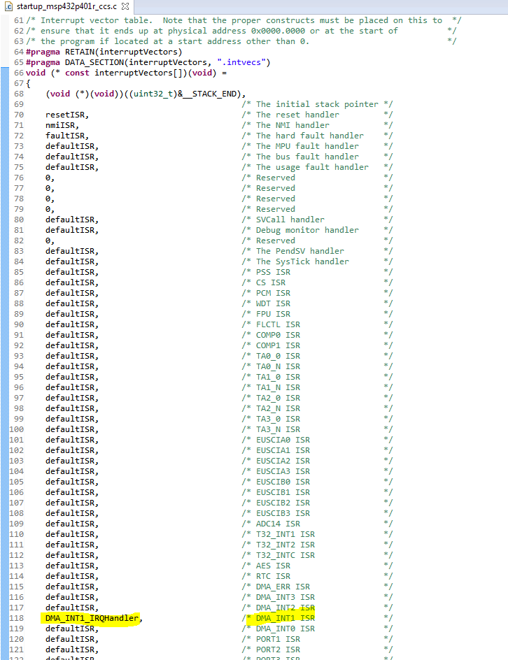
DMA_assignInterrupt(DMA_INT1, 0);
Interrupt_enableInterrupt(INT_DMA_INT1);I was planning to use the code above by filling the buffer "m_data_array" then calling DMA_enableChannel(0); although this didn't work.
How do i know when the buffer has been transmitted?


**Attention** This is a public forum