This thread has been locked.

If you have a related question, please click the "Ask a related question" button in the top right corner. The newly created question will be automatically linked to this question.

MSP430G2553 I2C to TCA8418 (reading registers and prescaling factor)

Other Parts Discussed in Thread: MSP430G2553, TCA8418

Hi,

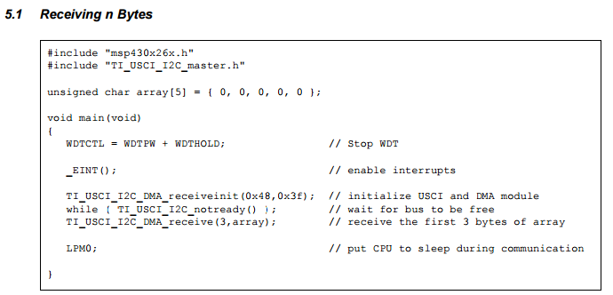
I'm trying to get a TCA8418 EVM/boosterpack to work with the MSP430G2553 launchpad from CCS. I'm using this TI guide to setup I2C:

http://www.ti.com/lit/an/slaa382a/slaa382a.pdf

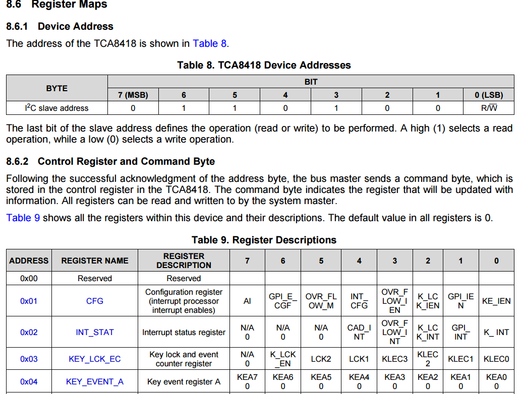
But I'm not exactly sure how to approach the actual reading from registers (I'm a complete I2C noobie). My understanding is I need to setup the USCI for transmitting, and then send the slave address (0x69 to read) to the device, and then after the acknowledgement bit I need to send the address of the register I'm supposed to read from. How do I "read" from the register like this - is the register's data sent back to me? Also, since I need to send the address of the register I'm reading from (snippet from the datasheet below), don't I need to be in transmit mode?

Could someone please kindly explain how to set the prescaling factor as needed in the TI reference code? 

Any help would be greatly appreciated, and thank you again!

  • Hi Oscar,

    So with the MSP430 using I2C, you may also want to see this code example: This code demonstrates a repeated start condition, which is what you use for an I2C read.

    Your main references are going to be the TCA8418 datasheet, and the MSP430G2553 user's guide www.ti.com/lit/pdf/slau144  chapter 17 USCI, I2C mode, because that has information on how to set up the MSP430 for I2C. Finally the code example that I linked above, or the code for the app note you linked www.ti.com/lit/zip/slaa382  can be used as a starting point.

    Basically, the TCA8418 will be your I2C slave. Looking in the datasheet for the TCA8418 on p. 24, it shows what a read transaction will look like. You can see that the 7-bit slave address is 0110100, and then there is a read/write bit. So for your MSP430 code, you'll want to set the MSP430 UCB0I2CSA slave address register as 0x34 when you are first initializing the module (you don't have to touch it after this, it will use it automatically). When you want to send a transmission, there is a bit in the UCBxCTL1 register UCTR - when it is set as 1, the module knows that you are trying to transmit to the slave, and when it is 0, it knows that you want to receive from the slave. The same UCB0CTL1 register also has a UCTXSTT bit - if this is set, a start bit will be sent (it will clear automatically after the start + address is sent). The UCTXIFG flag will indicate if the TX buffer is ready for you to write data into it.

    oscar yu said:
    My understanding is I need to setup the USCI for transmitting, and then send the slave address (0x69 to read) to the device, and then after the acknowledgement bit I need to send the address of the register I'm supposed to read from. How do I "read" from the register like this - is the register's data sent back to me? Also, since I need to send the address of the register I'm reading from (snippet from the datasheet below), don't I need to be in transmit mode?

    The MSP430 USCI module has a state machine that handles a lot of this for you. See www.ti.com/lit/pdf/slau144 section 17.3.4.2 Master Mode.

    1. At the beginning of your packet, you'll want to simply set UCTXSTT and UCTR, then load your register address for the TCA8418 that you are wanting to read into UCB0TXBUF. When you do this, the module will automatically send the Start bit, the slave address, get the ACK from the slave, and then send the byte that you loaded in the TX buffer (in this case, the address of what you are going to read in the next step).

    2. After you've done this, you need to issue what's called a repeated start condition, and then start receiving from the slave. You will do this simply by clearing the UCTR bit (so you will now be receiving) and setting UCTXSTT again. The module will automatically send the repeated start bit and the slave address again, get the ACK, and then your code should wait for the UCRXIFG to be set. The module will automatically clock the slave to do the read, and once the data is available in the MSP430 UCB0RXBUF, the receive interrupt is set and you can read it out. It will continue to try to receive data unless you set the UCTXSTP bit to generate the stop condition.

    I think you should be able to observe this type of methodology if you look at our code examples mentioned before, and I hope this helps make it clearer how it all works.

    oscar yu said:
    Could someone please kindly explain how to set the prescaling factor as needed in the TI reference code? 

    This is for setting the clock frequency that will be used by the I2C - you can see that the code for the app note you attached writes this value into the UCB0BR0 register, which you can look up in the user's guide www.ti.com/lit/pdf/slau144. Basically, you want to pass the value for how much you need to divide down your source clock to get the desired I2C frequency that you want to use. For example, if you have the USCI_B0 module being sourced from SMCLK, and you have SMCLK set to 8MHz from the DCO, then if you use a prescalar of 100 you'll get 80kHz for your I2C clock. To pick an I2C clock, you'll have to see what is allowed in the datasheet for your slave.

    Finally, please also note that you'll need some external pullup resistors on the I2C lines between your MSP and your TCA device.

    I hope that this helps to give you some pointers and get you started.

    Regards,

    Katie

  • Hi,

    Thank you for the reply! I'm using the example code as my base now, but I still had a few questions. How does the UCTXSTT/UCTR/UCB0TXBUF interact with the functions already present in the code? As in Setup_TX, Setup_RX, Transmit and Receive? I don't seem to pass any arguments so I assume there is some "external" control. Is this through UCTXSTT/UCTR/UCB0TXBUF as you mentioned? 

    I guess I'm wondering if I need to set UCTXSTT/UCTR as you mentioned to initialize or just call Setup_TX (though those bits don't seem to be set in that function, so I'm kinda confused as to what needs to be what when). 

    The user's guide also mentions certain things need to be set to select I2C Master Mode (UCMODEx, UCSYNC, UCMST, etc), but I can't find where this is set in the example I2C code provided? I think I'm possibly missing something?

    Sorry for the confusion, and thank you for the help so far!

    Oscar

  • Hi Katie,

    A short follow on question if I may:

    Regarding the I2C pullup resistors on clock & data...

    Is is possible to configure the internal port P1.x pullups (REN) instead of using external resistors?

    Thank you,

    O

  • The internal pullup resistors are rather weak (between 20 and 50 kΩ), so the raising edges of the I²C signals will become quite slow. You would need to lower the frequency of the USCI clock. (The exact number depends on the parasitic capacitances in your circuit; use an oscilloscope to check.)

  • Oscar, please have a look at my thread here.
    e2e.ti.com/.../477614
  • Hi Oscar,

    Are you still using the code example from the app note www.ti.com/.../slaa382 or were you using something else now? As a note as Raghava mentioned you could of course also use driverlib.

    For the code in the app note, I look in the folder slaa382a.zip\USCI I2C Master Library\without DMA support at the file TI_USCI_I2C_master.c. You can see that the function TI_USCI_I2C_transmitinit is setting the UCMST bit for master mode and the UCMODE_3 and UCSYNC bits for I2C.

    The UCTXSTT bit is not something that you want to set until right when you are about to start your packet sending or receiving. So it's not called in the init function but rather you'll see it gets set in TI_USCI_I2C_transmit, which is right before you are going to set your data.

    In this example, it is interrupt driven - so you'll see that the TI_USCI_I2C_transmit function only sets up the beginning of the transmission but does not set the UCTXBUF right away - rather what is going to happen is that the interrupt for UCTXIFG will fire, and then in the ISR for the interrupt is where UCB0TXBUF is filled with data. So if you look down in the ISR USCIAB0TX_ISR you'll see that the UCB0TXBUF is loaded with data there.

    The flow of the communication will be similar to the flow in the main.c from the same project I mentioned above, except that this project is receiving first and transmitting second. You're going to want to transmit the data indicating the register that you want to read from the TCA part, and then start the receive.

    For pullups - Clemens is right. You need to use external pullups. The internal pullups are meant more for keeping pins from floating or for getting interrupts off of a button etc, not for I2C. For I2C it is important to be able to control the size of the pullups because it will help you adjust to get a good waveform that doesn't look like a sawtooth or have a too-slow rise time, since the lines are all shared and you are only pulling down on them to communicate.

    Regards,
    Katie

**Attention** This is a public forum