- Ask a related questionWhat is a related question?A related question is a question created from another question. When the related question is created, it will be automatically linked to the original question.
Dear All
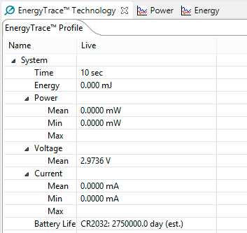
I am measuring the power consumption of MSP430FR5739 using a MSP-EXP430FR5739 board and a power monitor (Monson Solutions Inc.). The program I am running is the example MSP430FR57xx_LPM4.c from here, and whose code, for ease of reference is:
#include <msp430.h>

int main(void)
{
  WDTCTL = WDTPW + WDTHOLD;                 // Stop WDT

  P1DIR = 0;
  P1OUT = 0;
  P1REN = 0xFF;

  P2DIR = 0;
  P2OUT = 0;
  P2REN = 0xFF;

  P3DIR = 0;
  P3OUT = 0;
  P3REN = 0xFF;

  P4DIR = 0;
  P4OUT = 0;
  P4REN = 0xFF;

  CSCTL0_H = 0xA5;
  CSCTL1 |= DCOFSEL0 + DCOFSEL1;             // Set max. DCO setting
  CSCTL2 = SELA_1 + SELS_3 + SELM_3;        // set ACLK = VLO; MCLK = DCO
  CSCTL3 = DIVA_0 + DIVS_1 + DIVM_1;        // set all dividers

  CSCTL4 = XT1OFF + XT2OFF;
  CSCTL5 &= ~(XT1OFFG + XT2OFFG);

  PJDIR = 0;
  PJOUT = 0;
  PJREN = 0xFF;

  REFCTL0 |= REFTCOFF;
  REFCTL0 &= ~REFON;

  __bis_SR_register(LPM4_bits);

}
As seen, this basically puts the MSP430FR5739 in LMP4.
The problem I am having is that I cannot get the correct power consumption value because when I power the experimenter board, it does power both the MSP430FR5739 and the debugging/programming interface. The debugging and programming interface consists of, according to the schematics in slau343b.pdf, a MSP430F16X and other components connected to it, among others a LED (led0 in the board).
When powering the experimenter board, this led remains always ON, indicating the the board is effectively powered. Besides the fact that I don't know what other components from the debugging/programming interface are being powered, I would like just to power the MSP430FR5730 solely with a CC25xx RF I have connected to the board.
Also worth mentioning I am powering the board using the VCC and GND pins available where you can connect a RF radio, and next to MSP_PWR and RF_PWR. I have connected the power monitor to MSP_PWR in an attempt to measure the both current and power of the MSP430FR5739. But I would need to use the board without the debugging interface for further experimentation. That's why I would like to disable it, if possible.
I would appreciate your help with this. Many thanks.
Best regards,
David
Edit: Below a photo of my setup:

From left to right, red (VCC) and black (GND) to power the debugger/programming interface. Red (VCC_MSP) and brown (RF_PWR -only pin 2-) to power the MSP430FR5739 and the RF CC25xx I am using.
My question is, why do I have to power the debugger/programmer as well? If I disconnect MSP_PWR and RF_PWR from the electric power source, only the debugger/programming interface is working, and I cannot find the way to power only the rest of the board without such interface. I cannot figure this out from schematics either.
**Attention** This is a public forum