Hello All,
I want to detect power supply fall and write data to Internal Flash memory.
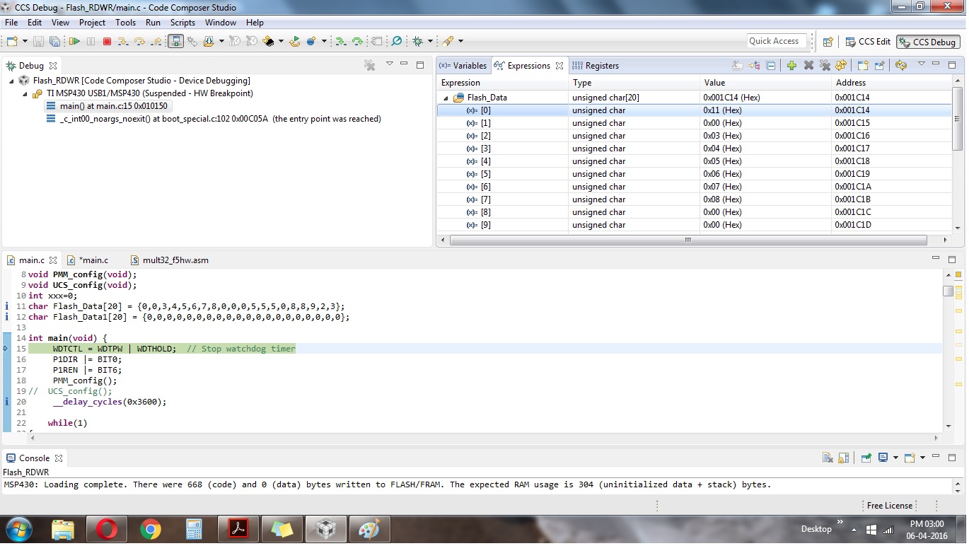
Actually problem is my code is going in ISR at power ON instead power OFF.
Here is my code
#include <msp430.h>
/*
* main.c
*/
void write_SegC(void);
void copy_from_FlashC(void);
void PMM_config(void);
void UCS_config(void);
char Flash_Data[20] = {0,0,3,4,5,6,7,8,0,0,0,5,5,5,0,8,8,9,2,3};
char Flash_Data1[20] = {0,0,0,0,0,0,0,0,0,0,0,0,0,0,0,0,0,0,0,0};
int main(void) {
WDTCTL = WDTPW | WDTHOLD; // Stop watchdog timer
P1DIR |= BIT0;
P1REN |= BIT6;
UCS_config();
PMM_config();
UCS_config();
while(1)
{
copy_from_FlashC();
}
return 0;
}
void copy_from_FlashC(void)
{
unsigned int i;
char *Flash_ptrC;
// char *Flash_ptrD;
Flash_ptrC = (char *) 0x1880; // Initialize Flash segment C ptr
// Flash_ptrD = (char *) 0x1800; // Initialize Flash segment D ptr
// Flash_ptrD = (char*) Flash_Data[0];
FCTL3 = FWKEY; // Clear Lock bit
// FCTL1 = FWKEY | ERASE; // Set Erase bit
// *Flash_ptrD = 0; // Dummy write to erase Flash seg D
// FCTL1 = FWKEY | WRT; // Set WRT bit for write operation
FCTL1 = FWKEY;
FCTL4 = FWKEY | MGR0 ;
for (i = 0; i < 20; i++)
{
// *Flash_ptrD++ = *Flash_ptrC++; // copy value segment C to seg D
Flash_Data1[i] = *Flash_ptrC++;
}
FCTL1 = FWKEY; // Clear WRT bit
FCTL3 = FWKEY | LOCK; // Set LOCK bit
}
void write_SegC(void)
{
P1OUT |= BIT0;
unsigned int i;
char *Flash_ptr; // Initialize Flash pointer
Flash_ptr = (char *)0x1880;
FCTL3 = FWKEY; // Clear Lock bit
FCTL1 = FWKEY | ERASE; // Set Erase bit
*Flash_ptr = 0; // Dummy write to erase Flash seg
FCTL1 = FWKEY | WRT; // Set WRT bit for write operation
for (i = 0; i < 20; i++)
{
*Flash_ptr++ = Flash_Data[i]; // Write value to flash
}
FCTL1 = FWKEY; // Clear WRT bit
FCTL3 = FWKEY | LOCK; // Set LOCK bit
P1OUT &= ~BIT0;
}
void PMM_config(void)
{
//unlock PMM
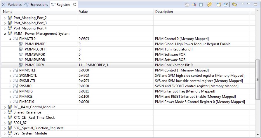
PMMCTL0_H=PMMPW_H;
PMMCTL0_L|=PMMCOREV_3;
//check voltage level
switch(PMMCTL0&PMMCOREV_3)
{
//settings for highest core voltage settings
case PMMCOREV_3:
//setup high side supervisor and monitor
SVSMHCTL=SVMHE|SVSHE|SVSHRVL_3|SVSMHRRL_7;
break;
}
//clear interrupt flags
PMMIFG&=~(SVMLIFG|SVMHIFG|SVMHVLRIFG|SVMLVLRIFG);
//setup interrupts
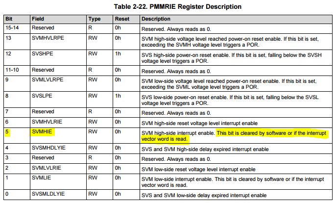
PMMRIE|=SVMLIE|SVMHIE|SVMHVLRIE|SVMLVLRIE;
//lock PMM
PMMCTL0_H=0;
}
#pragma vector = SYSNMI_VECTOR
__interrupt void SYS_NMI(void)
{
switch(SYSSNIV)
{
//core supply voltage monitor interrupt
case SYSSNIV_SVMLIFG:
//event to report error
//set flag
break;
//input supply voltage monitor interrupt
case SYSSNIV_SVMHIFG:
write_SegC();
// Clear_SegC(value); // For testing only
//event to report error
//set flag
break;
//core supply voltage monitor delay interrupt
case SYSSNIV_DLYLIFG:
break;
//interrupt supply voltage monitor delay interrupt
case SYSSNIV_DLYHIFG:
break;
//Vacant memory access interrupt
case SYSSNIV_VMAIFG:
break;
//JTAG mailbox in interrupt
case SYSSNIV_JMBINIFG:
break;
//JTAG mailbox out interrupt
case SYSSNIV_JMBOUTIFG:
break;
//SVMLVLRIFGSVMHVLRIFG
case SYSSNIV_VLRLIFG:
//clear interrupt flag bits
//unlock PMM
PMMCTL0_H=PMMPW_H;
//clear interrupt flags
PMMIFG&=~(SVMLIFG|SVMLVLRIFG);
//lock PMM
PMMCTL0_H=0;
break;
//SVMHVLRIFGSVMHVLRIFG
case SYSSNIV_VLRHIFG:
//clear interrupt flag bits
//unlock PMM
PMMCTL0_H=PMMPW_H;
//clear interrupt flags
PMMIFG&=~(SVMHIFG|SVMHVLRIFG);
//lock PMM
PMMCTL0_H=0;
break;
}
}
void UCS_config(void)
{
PMMCTL0_H = 0xA5;
PMMCTL0_L = 0x03;
UCSCTL0 = UCSCTL0 | 0x1F00;
UCSCTL1 = UCSCTL1 & 0x0000;
UCSCTL1 = UCSCTL1 | 0x0040;
UCSCTL2 = UCSCTL2 & 0x0000 ; // FLL Divider
UCSCTL2 = UCSCTL2 | 0x304F ; // for 20 MHz MCLK and 2.6 MHz SMCLK
UCSCTL3 = 0x0000;
UCSCTL4 = UCSCTL4 & 0X0000;
UCSCTL4 = UCSCTL4 | 0X0043;
}
Thanks in Advance
Regards
Abhishek Parikh