


Hi, I am using MSP430FR5730 for a shutter glass micocontroller. I need to capture IR LOW signal as interrupts.(120 Hz). So, I took Port2.1 as TimerB0 CCR0 capture as it is pointed in the datasheet below:

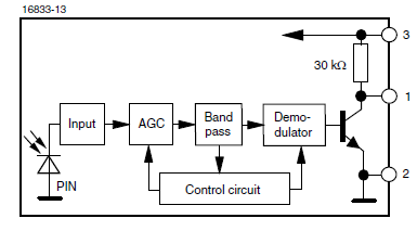
I am using MSP430 driver library. I set up continious mode for capture, I started captureand I choosed falling edge since I use this IR receiver below(1 is output)
So nothing is wrong on Hardware side. But I never catch the capture eventhough I monitor the IR output and IR works very fine. There must be something I missed in the code. Could you please help me? Here is my code:
#include "driverlib.h"
#include "msp430.h"
#include "msp430fr5730.h"

int tester = 0;
int tester2 = 0;
int temp;
int i;
int garbageTime;
_Bool state=0;
uint8_t orient = 0;
uint16_t capVal = 0;
uint16_t leftPack[4];
uint16_t rightPack[6];

#define TB2_BaseAddress 0x0440
#define TB0_BaseAddress 0x03C0
#define TA0_BaseAddress 0x0340
#define NO_Orientation 0x00
#define LEFT_Orientation 0x0A
#define RIGHT_Orientation 0x0B

/*   USEFUL TIMERB METHODS
 *
 * 	Timer_B_getCaptureCompareCount(uint16_t baseAddress, uint16_t captureCompareRegister);
 * 	Timer_B_getCounterValue(uint16_t baseAddress);
 *  Timer_B_clearCaptureCompareInterrupt(uint16_t baseAddress, uint16_t captureCompareRegister);
 *  Timer_B_clearTimerInterrupt(uint16_t baseAddress);
 *  Timer_B_clear(uint16_t baseAddress);
 *  Timer_B_getCaptureCompareInterruptStatus(uint16_t baseAddress, uint16_t captureCompareRegister, uint16_t mask);
 *  Timer_B_disableCaptureCompareInterrupt(uint16_t baseAddress, uint16_t captureCompareRegister);
 *  Timer_B_enableCaptureCompareInterrupt(uint16_t baseAddress, uint16_t captureCompareRegister);
 *  Timer_B_getInterruptStatus(uint16_t baseAddress);
 *  Timer_B_disableInterrupt(uint16_t baseAddress);
 *  Timer_B_enableInterrupt(uint16_t baseAddress);
 *  Timer_B_initCaptureMode(uint16_t baseAddress, sTimer_B_initCaptureModeParam *param);
 *  Timer_B_startCounter(uint16_t baseAddress, uint16_t timerMode);
*/

/*   USEFUL TIMERA METHODS
 *	Timer_A_startCounter(uint16_t baseAddress, uint16_t timerMode);
 *	Timer_A_initUpMode(uint16_t baseAddress, Timer_A_initUpModeParam *param);
 *	Timer_A_enableInterrupt(uint16_t baseAddress);
 *	Timer_A_disableInterrupt(uint16_t baseAddress);
 *	Timer_A_getInterruptStatus(uint16_t baseAddress);
 *	Timer_A_enableCaptureCompareInterrupt(uint16_t baseAddress, uint16_t captureCompareRegister);
 *	Timer_A_disableCaptureCompareInterrupt(uint16_t baseAddress, uint16_t captureCompareRegister);
 *	Timer_A_getCaptureCompareInterruptStatus(uint16_t baseAddress, uint16_t captureCompareRegister, uint16_t mask);
 *	Timer_A_clear(uint16_t baseAddress);
 *	Timer_A_getCaptureCompareCount(uint16_t baseAddress, uint16_t captureCompareRegister);
 *	Timer_A_stop(uint16_t baseAddress);
 *	Timer_A_setCompareValue(uint16_t baseAddress, uint16_t compareRegister, uint16_t compareValue);
 *	Timer_A_clearTimerInterrupt(uint16_t baseAddress);
 *	Timer_A_clearCaptureCompareInterrupt(uint16_t baseAddress, uint16_t captureCompareRegister);
 *	Timer_A_getCounterValue(uint16_t baseAddress);
 *
 *
 *
 */

/*    USEFUL GPIO METHODS
 *	GPIO_setAsOutputPin(uint8_t selectedPort, uint16_t selectedPins);
 *	GPIO_setAsInputPin(uint8_t selectedPort, uint16_t selectedPins);
 *	GPIO_setOutputHighOnPin(uint8_t selectedPort, uint16_t selectedPins);
 *	GPIO_setOutputLowOnPin(uint8_t selectedPort, uint16_t selectedPins);
 *	GPIO_getInputPinValue(uint8_t selectedPort, uint16_t selectedPins);
 *	GPIO_enableInterrupt(uint8_t selectedPort, uint16_t selectedPins);
 *	GPIO_disableInterrupt(uint8_t selectedPort, uint16_t selectedPins);
 *	GPIO_getInterruptStatus(uint8_t selectedPort, uint16_t selectedPins);
 *	GPIO_clearInterrupt(uint8_t selectedPort, uint16_t selectedPins);
 *	GPIO_selectInterruptEdge(uint8_t selectedPort, uint16_t selectedPins, uint8_t edgeSelect);
 *
 *
 *
 *
 */


void setClock(void);
void setInterrupts(void);
void setOutputs(void);
void setInputs(void);
void setTimer(void);
void setCapComp(void);
void outRL(_Bool sw);
void setTimerAUp(void);

int main(void) {

    WDT_A_hold(WDT_A_BASE);
	//WDTCTL = WDTPW | WDTHOLD;
    /*
	P2OUT &= ~BIT2;
	P2OUT &= ~BIT0;

    P2DIR |= BIT2 | BIT0;
    P2OUT |= BIT2 | BIT0;
     */
    //setInterrupts();
    setOutputs();
    //setInputs();
    setTimer();
    setCapComp();
    setContMode();
    startTimer();
    setTimerAUp();
    GPIO_setOutputLowOnPin(GPIO_PORT_PJ, GPIO_PIN3 | GPIO_PIN2 | GPIO_PIN0); //Set EN0, CE and SYSOFF  to LOW
    GPIO_setOutputHighOnPin(GPIO_PORT_PJ, GPIO_PIN1);  // Set EN1 to HIGH
    temp = 0;
    //__bis_SR_register(LPM0 | GIE);
    __enable_interrupt();
    while(1)
    {
    }

}
#pragma vector=TIMER0_A0_VECTOR
__interrupt void Timer_A(void)
{
	//
	tester += 1;
	if(state == 1)
	{
		//
		outRL(1);  // Left eye open
		Timer_A_stop(TA0_BaseAddress);
		Timer_A_clear(TA0_BaseAddress);
		Timer_A_clearTimerInterrupt(TA0_BaseAddress);
		state = 0;
	}
	else
	{
		//
		Timer_A_stop(TA0_BaseAddress);
		Timer_A_clear(TA0_BaseAddress);
		Timer_A_clearTimerInterrupt(TA0_BaseAddress);
	}
}

#pragma vector=TIMER0_B0_VECTOR
__interrupt void Timer_B(void)
{
	//
	tester2 += 1;
	capVal = Timer_B_getCaptureCompareCount(TB0_BaseAddress, TIMER_B_CAPTURECOMPARE_REGISTER_0);
	if(capVal > 934375/120 - 934375/600)
	{
		//
		state = 1;
		Timer_B_clear(TB0_BaseAddress);
		Timer_B_clearCaptureCompareInterrupt(TB0_BaseAddress, TIMER_B_CAPTURECOMPARE_REGISTER_0);
		Timer_B_clearTimerInterrupt(TB0_BaseAddress);
		Timer_A_clear(TA0_BaseAddress);
		Timer_A_clearTimerInterrupt(TA0_BaseAddress);
		Timer_A_startCounter(TA0_BaseAddress, TIMER_A_UP_MODE);
	}
	else if(capVal <= 113 && state == 1)  // if first bit was for left orientation 40 us
	{
		//
		i = 0;
		orient = LEFT_Orientation;
		Timer_B_clear(TB0_BaseAddress);
		Timer_B_clearCaptureCompareInterrupt(TB0_BaseAddress, TIMER_B_CAPTURECOMPARE_REGISTER_0);
		Timer_B_clearTimerInterrupt(TB0_BaseAddress);
		outRL(0);  // Left eye open
		state = 0;
	}
}

void setClock(void)
{
	//DCO set to 24 MHz
	CS_setDCOFreq(CS_DCORSEL_1,
				  CS_DCOFSEL_3);
	// SMCLK sourced by DCO and divided to 32*2
	CS_initClockSignal(CS_SMCLK,
			CS_DCOCLK_SELECT,
			CS_CLOCK_DIVIDER_32);
	//Turn on SMCLK
	CS_turnOnSMCLK();
	//1.33 uS is the cycle step
}

void setInterrupts(void)
{
	// First clear the interrupts
	GPIO_clearInterrupt(GPIO_PORT_P2,
						GPIO_PIN1 | GPIO_PIN2);
	// IR_OUT and PGOOD set as interrupt
	GPIO_enableInterrupt(GPIO_PORT_P2,
						 GPIO_PIN1 | GPIO_PIN2);
	// IR and PGOOD outs as selected high to low interrupts
	GPIO_selectInterruptEdge(GPIO_PORT_P2,
							 GPIO_PIN1 | GPIO_PIN2,
							 GPIO_HIGH_TO_LOW_TRANSITION);

}


void setOutputs(void)
{
	// Port 1, 0 to 7 pins are outputs to gate driver
	GPIO_setAsOutputPin(GPIO_PORT_P1,
						GPIO_PIN0 | GPIO_PIN1 | GPIO_PIN2 | GPIO_PIN3 | GPIO_PIN4 | GPIO_PIN5 | GPIO_PIN6 | GPIO_PIN7);
	GPIO_setAsOutputPin(GPIO_PORT_PJ,
						GPIO_PIN0 | GPIO_PIN1 | GPIO_PIN2 | GPIO_PIN3);
}


void setInputs(void)
{
	// PGOOD!, CHG! and IR_OUT set as inputs
	GPIO_setAsInputPin(GPIO_PORT_P2,
					   GPIO_PIN0 | GPIO_PIN1 | GPIO_PIN2);
}

void setTimer(void)
{
	//
	Timer_B_stop(TB0_BaseAddress);
	Timer_B_clearTimerInterrupt(TB0_BaseAddress);
}

void startTimer(void)
{
	//
	Timer_B_clear(TB0_BaseAddress);
	Timer_B_startCounter(TB0_BaseAddress, TIMER_B_CONTINUOUS_MODE);
}

void setCapComp(void)
{
	//
	Timer_B_initCaptureModeParam timerConfig_1 =
	{
		//
		TIMER_B_CAPTURECOMPARE_REGISTER_0,
		//TIMER_B_CAPTUREMODE_RISING_AND_FALLING_EDGE,
		TIMER_B_CAPTUREMODE_FALLING_EDGE,
		TIMER_B_CAPTURE_INPUTSELECT_CCIxA,
		TIMER_B_CAPTURE_ASYNCHRONOUS,
		TIMER_B_CAPTURECOMPARE_INTERRUPT_ENABLE,
		//TIMER_B_OUTPUTMODE_TOGGLE_RESET
		TIMER_B_OUTPUTMODE_SET
	};
	//Configure TB2in capture mode like pointed in timerConfig1 module
	Timer_B_initCaptureMode(TB0_BaseAddress,
	                        &timerConfig_1);
	// Select TimerB Counter length
	Timer_B_selectCounterLength(TB0_BaseAddress,
								TIMER_B_COUNTER_16BIT);
	// Enable interrupt for timerB2 module
	Timer_B_enableInterrupt(TB0_BaseAddress);
	Timer_B_enableCaptureCompareInterrupt(TB0_BaseAddress,
										  TIMER_B_CAPTURECOMPARE_REGISTER_0);

}

void setTimerAUp(void)
{
	//First stop timer A
	Timer_A_stop(TA0_BaseAddress);
	//

	Timer_A_initUpModeParam timerAUp =
	{
			//
			TIMER_A_CLOCKSOURCE_SMCLK,
			TIMER_A_CLOCKSOURCE_DIVIDER_1,
			//((24000000/64)/2)/120,
			127,
			TIMER_A_TAIE_INTERRUPT_ENABLE,
			TIMER_A_CCIE_CCR0_INTERRUPT_ENABLE,
			TIMER_A_DO_CLEAR,
			1
	};
	//initialize timer module
	Timer_A_initUpMode(TA0_BaseAddress, &timerAUp);
	//enable interrupt
	Timer_A_enableInterrupt(TA0_BaseAddress);
	//enable general interrupts
	//__enable_interrupt();
	//Start TimerA Up mode
	//Timer_A_startCounter(TA0_BaseAddress, TIMER_A_UP_MODE);
}

void setContMode(void)
{
	//
	Timer_B_initContinuousModeParam timerContConfig =
	{
		TIMER_B_CLOCKSOURCE_SMCLK,
		TIMER_B_CLOCKSOURCE_DIVIDER_1,  // 934375 Hz measured
		TIMER_B_TBIE_INTERRUPT_DISABLE,
		TIMER_B_DO_CLEAR,
		1
	};

	Timer_B_initContinuousMode(TB0_BaseAddress, &timerContConfig);
}

void outRL(_Bool sw)
{
	//
	if(sw)
	{
		//
		GPIO_setOutputHighOnPin(GPIO_PORT_P1, GPIO_PIN4 | GPIO_PIN5);
		GPIO_setOutputLowOnPin(GPIO_PORT_P1, GPIO_PIN6 | GPIO_PIN7);
	}
	else
	{
		//GPIO_PIN6 | GPIO_PIN7
		GPIO_setOutputHighOnPin(GPIO_PORT_P1, GPIO_PIN6 | GPIO_PIN7);
		GPIO_setOutputLowOnPin(GPIO_PORT_P1, GPIO_PIN4 | GPIO_PIN5);
	}
}

