This thread has been locked.

If you have a related question, please click the "Ask a related question" button in the top right corner. The newly created question will be automatically linked to this question.

Problem using DriverLib in I2C polled mode on MSP432 Launchpad

Other Parts Discussed in Thread: TMP007

Hi folks,

I am trying to do some simple, polled (not interrupt) write and read transfers using the EUSCI_B1 module on the MSP432 with DriverLib.  However, I have run into behavior that I cannot explain, and hope that one of you might have some ideas to try.

I'm communicating with a TI TMP007 temperature sensor.  To get a baseline and some ideas on communicating with the device, I purchased a module from Adafruit and connected it to an Arduino using their TMP007 library.  I then connected the I2C lines to my Intronix LogicPort LA1034 Logic Analyzer, which has a built in I2C decoder.  The resulting capture from initialization is attached as ArduinoI2CStartup.PNG.

It's a bit of an eye test to show all of the initial data, but here is a summary.  The TMP007 is at I2C address 0x40.  There are 4 key transactions:

1) Configure the TMP007 by writing 0x1140 to configuration register 0x02.  This results in a write of 0x40, 0x02, 0x11, 0x40.

2) Configure the status mask register 0x05 by writing 0xC000 to it.  This results in a write of 0x40, 0x05, 0xC0, 0x00.

3) Select the device ID register 0x1F by writing that to the TMP007.  This results in a write of 0x40, 0x1F.

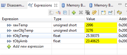
4) Read the device ID, which should be 0x0078.  This results in a read of 0x40, 0x00, 0x78.

All of this looks great on the Arduino.  However, when I try to do the same using polled DriverLib methods, the transfers do not take place correctly, and I cannot figure out why.

My master configuration structure looks like this:

masterConfig.selectClockSource = EUSCI_B_I2C_CLOCKSOURCE_SMCLK;
masterConfig.i2cClk = 48000000;
masterConfig.dataRate = EUSCI_B_I2C_SET_DATA_RATE_100KBPS;
masterConfig.byteCounterThreshold = 0;
masterConfig.autoSTOPGeneration = EUSCI_B_I2C_NO_AUTO_STOP;

So far so good.  Then I tried wading through the documentation for DriverLib regarding the I2C master mode operation, and came up with the following (very brute force, but I wanted to keep it simple:

// 1. Configure TMP007
        
/* Making sure the last transaction has been completely sent out */
while (MAP_I2C_masterIsStopSent(EUSCI_B1_BASE) == EUSCI_B_I2C_SENDING_STOP);
        
MAP_I2C_setSlaveAddress(EUSCI_B1_BASE, 0x40);
MAP_I2C_setMode(EUSCI_B1_BASE, EUSCI_B_I2C_TRANSMIT_MODE);
        
MAP_I2C_masterSendMultiByteStart(EUSCI_B1_BASE, 0x02);
MAP_I2C_masterSendMultiByteNext(EUSCI_B1_BASE, 0x11);
MAP_I2C_masterSendMultiByteNext(EUSCI_B1_BASE, 0x40);
MAP_I2C_masterSendMultiByteStop(EUSCI_B1_BASE);
        
/* Making sure the last transaction has been completely sent out */
while (MAP_I2C_masterIsStopSent(EUSCI_B1_BASE) == EUSCI_B_I2C_SENDING_STOP);

// 2. Set status mask
        
MAP_I2C_masterSendMultiByteStart(EUSCI_B1_BASE, 0x05);
MAP_I2C_masterSendMultiByteNext(EUSCI_B1_BASE, 0xC0);
MAP_I2C_masterSendMultiByteNext(EUSCI_B1_BASE, 0x00);
MAP_I2C_masterSendMultiByteStop(EUSCI_B1_BASE);
        
/* Making sure the last transaction has been completely sent out */
while (MAP_I2C_masterIsStopSent(EUSCI_B1_BASE) == EUSCI_B_I2C_SENDING_STOP);

// 3. Point to device ID
        
MAP_I2C_masterSendSingleByte(EUSCI_B1_BASE, 0x1F);
        
/* Making sure the last transaction has been completely sent out */
while (MAP_I2C_masterIsStopSent(EUSCI_B1_BASE) == EUSCI_B_I2C_SENDING_STOP);

// 4. Read device ID
        
MAP_I2C_setMode(EUSCI_B1_BASE, EUSCI_B_I2C_RECEIVE_MODE);
        
MAP_I2C_masterReceiveStart(EUSCI_B1_BASE);
uint8_t msb = MAP_I2C_masterReceiveMultiByteNext(EUSCI_B1_BASE);
uint8_t lsb = MAP_I2C_masterReceiveMultiByteFinish(EUSCI_B1_BASE);
MAP_I2C_masterReceiveMultiByteStop(EUSCI_B1_BASE);

/* Making sure the last transaction has been completely sent out */
while (MAP_I2C_masterIsStopSent(EUSCI_B1_BASE) == EUSCI_B_I2C_SENDING_STOP);

uint16_t data = ((uint16_t)msb << 8) | lsb;

This _seems_ straightforward.  It sets the slave address, selects 0x40 as the slave address, and selects master transmit mode.  It then tries to write the same 1st 3 transactions as the Arduino example.   Then it changes to master receive mode, and tries to read the two bytes representing the device ID.

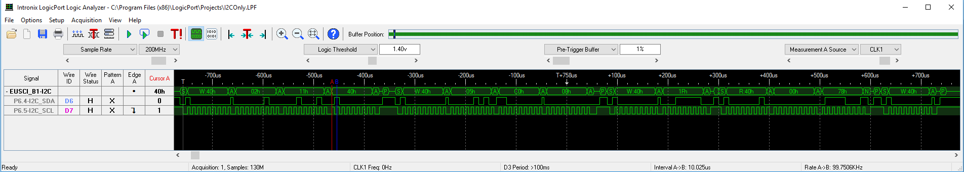
Here is the data captures with my logic analyzer (sorry,  another eye test!).

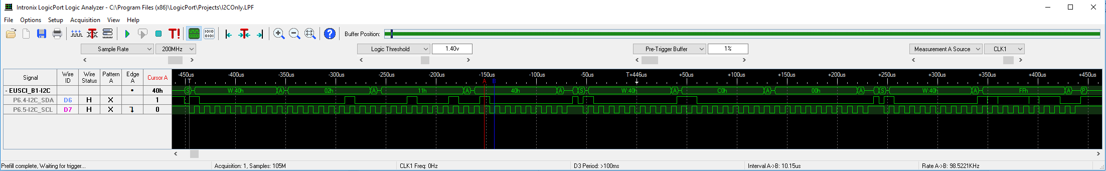
The first two transfers look about the same, 1) a write of 0x40, 0x02, 0x11, 0x40, then 2) a write of 0x40, 0xC0, 0x00.  However, in the 2nd transaction, the write of 0x05 after the slave address of 0x40 is completely missing!  Then it appears that the 3) transaction is a write of 0x40, 0xFF, which is NOT the address of the device ID, 0x1F.

This code seems so simple, but the examples do not provide much help for polled operation of the I2C master.  Instead, they use interrupts and go to sleep, which just complicates the example and detracts from understanding how the code works.

Further, there don't seem to be any good examples where there are multibyte writes, then a single byte write, followed by a multibyte read, so it's very hard to tell if I am using DriverLib as expected.

I know this is a lot of information, but I am truly stuck, and hope that someone in the community who knows the I2C interface and DriverLib can help me out.

Many thanks for your help!

Scott

  • Hi all,

    As I thought about this some more, it occurred to me that what _might_ be happening is that the DriverLib calls to send bytes are executing so fast that the transmit data is being overwritten before it can be fully sent out. It appears that once the data is transferred from the UCBxTXBUF register buffer into the shift register, UCTXIFG0 is set, per the Family Technical Reference Manual.

    Is it possible that I'm sending new bytes before this flag is set? I believe that an interrupt request will be generated if the UCTXIEx bit is set, although I am not sure exactly which of those bits should be set.

    Is there a way to poll using DriverLib to make sure that the byte has been sent, or is the only way to do this through the interrupt? It seems that the (less that wonderfully instructive) DriverLib examples make use of the interrupt, so maybe I am trying to do something unanticipated by using DriverLib I2c in the polled manner.

    I'm used to UARTs that have some type of "TxBUF Register Empty" flag to indicate when it's ok to load another data byte. Any ideas on how to get such information using the calls available through DriverLib?

    Thanks again for your consideration, and Happy Holiday!

    Scott
  • Hi Scott,

    Scott Whitney80914 said:
    Hi all,

    As I thought about this some more, it occurred to me that what _might_ be happening is that the DriverLib calls to send bytes are executing so fast that the transmit data is being overwritten before it can be fully sent out. It appears that once the data is transferred from the UCBxTXBUF register buffer into the shift register, UCTXIFG0 is set, per the Family Technical Reference Manual.

    I think that is unlikely, as the driverlib calls you are using are polling the TX flags whether the data has been already sent. So in theory, this should not happen.

    Since I am no expert on the driverlib, I would suggest to step through the execution with a debugger and monitor the eUSCI_B flags.

    Cheers,

    Dan

  • Dan, thanks for your reply. I figured out how to step into the DriverLib code by loading the symbols from the *driverlib.out file provided by TI into the IAR debugger. So that should be some progress, but things still are confusing.

    I am really confused by one of the interrupt flags, UCBIT9IFG. It appears that this flag is being set, however I do not know what it means, and the documentation on the MSP432 and the DriverLib really doesn't discuss it. The family reference manual only says:

    Bit 14 UCBIT9IFG RW Reset value:0h Bit position 9 interrupt flag 0b = No interrupt pending 1b = Interrupt pending

    I know that I2C can support 7 bit addressing and 10 bit addressing. How is that controlled in DriverLib? I can't seem to figure out why this UCBIT9IFG interrupt flag would be set by any of my transfers.

    Further, I added a simple printf dump of the EUSCI_B1 register values, and it appears that under some conditions, I can see that 3 data bytes have been transmitted, but the UBCNT only indicates that 2 bytes have been transmitting.

    Here is my dumpI2CRegisters() function, pretty straightforward:

    void dumpI2CRegisters(void)
    {
        uint16_t ctlw0      = EUSCI_B1->CTLW0;      /**< eUSCI_Bx Control Word Register 0 */
        uint16_t ctlw1      = EUSCI_B1->CTLW1;      /**< eUSCI_Bx Control Word Register 1 */
        uint16_t brw        = EUSCI_B1->BRW;        /**< eUSCI_Bx Baud Rate Control Word Register */
        uint16_t statw      = EUSCI_B1->STATW;      /**< eUSCI_Bx Status Register */
        uint16_t tbcnt      = EUSCI_B1->TBCNT;      /**< eUSCI_Bx Byte Counter Threshold Register */
        uint16_t rxbuf      = EUSCI_B1->RXBUF;      /**< eUSCI_Bx Receive Buffer Register */
        uint16_t txbuf      = EUSCI_B1->TXBUF;      /**< eUSCI_Bx Transmit Buffer Register */
        uint16_t i2coa0     = EUSCI_B1->I2COA0;     /**< eUSCI_Bx I2C Own Address 0 Register */
        uint16_t i2coa1     = EUSCI_B1->I2COA1;     /**< eUSCI_Bx I2C Own Address 1 Register */
        uint16_t i2coa2     = EUSCI_B1->I2COA2;     /**< eUSCI_Bx I2C Own Address 2 Register */
        uint16_t i2coa3     = EUSCI_B1->I2COA3;     /**< eUSCI_Bx I2C Own Address 3 Register */
        uint16_t addrx      = EUSCI_B1->ADDRX;      /**< eUSCI_Bx I2C Received Address Register */
        uint16_t addrmask   = EUSCI_B1->ADDMASK;    /**< eUSCI_Bx I2C Address Mask Register */
        uint16_t i2csa      = EUSCI_B1->I2CSA;      /**< eUSCI_Bx I2C Slave Address Register */
        uint16_t ie         = EUSCI_B1->IE;         /**< eUSCI_Bx Interrupt Enable Register */
        uint16_t ifg        = EUSCI_B1->IFG;        /**< eUSCI_Bx Interrupt Flag Register */
        uint16_t iv         = EUSCI_B1->IV;         /**< eUSCI_Bx Interrupt Vector Register */
        printf("ctlw0 = 0x%04X ctlw1 = 0x%04X, brw = 0x%04X, statw = 0x%04X, tbcnt = 0x%04X, rxbuf = 0x%04X, txbuf = 0x%04X, ie = 0x%04X, ifg = 0x%04X\n\r",
               ctlw0, ctlw1, brw, statw, tbcnt, rxbuf, txbuf, ie, ifg);
    }
    

    Here is the simple code to try to write two sequences of 3 data bytes each (plus the 0x40 slave address):

            MAP_I2C_setSlaveAddress(EUSCI_B1_BASE, 0x40);
            MAP_I2C_setMode(EUSCI_B1_BASE, EUSCI_B_I2C_TRANSMIT_MODE);
            
            /* Making sure the last transaction has been completely sent out */
            while (MAP_I2C_masterIsStopSent(EUSCI_B1_BASE) == EUSCI_B_I2C_SENDING_STOP);
            
            MAP_I2C_masterSendMultiByteStart(EUSCI_B1_BASE, 0x02);
            MAP_I2C_masterSendMultiByteNext(EUSCI_B1_BASE, 0x11);
            MAP_I2C_masterSendMultiByteFinish(EUSCI_B1_BASE, 0x40);
            
            dumpI2CRegisters();
            
            /* Making sure the last transaction has been completely sent out */
            while (MAP_I2C_masterIsStopSent(EUSCI_B1_BASE) == EUSCI_B_I2C_SENDING_STOP);
    
            dumpI2CRegisters();
            
            MAP_I2C_masterSendMultiByteStart(EUSCI_B1_BASE, 0x05);
            MAP_I2C_masterSendMultiByteNext(EUSCI_B1_BASE, 0xC0);
            MAP_I2C_masterSendMultiByteFinish(EUSCI_B1_BASE, 0x00);
            
            dumpI2CRegisters();
            
            /* Making sure the last transaction has been completely sent out */
            while (MAP_I2C_masterIsStopSent(EUSCI_B1_BASE) == EUSCI_B_I2C_SENDING_STOP);
    
            dumpI2CRegisters();


    When I run this, here is the output I get for each of the calls to dumpI2CRegisters():

    ctlw0 = 0x0F94 ctlw1 = 0x0000, brw = 0x01E0, statw = 0x0210, tbcnt = 0x0000, rxbuf = 0x0000, txbuf = 0x0040, ie = 0x0000, ifg = 0x4002
    ctlw0 = 0x0F90 ctlw1 = 0x0000, brw = 0x01E0, statw = 0x0300, tbcnt = 0x0000, rxbuf = 0x0000, txbuf = 0x0040, ie = 0x0000, ifg = 0x400A
    ctlw0 = 0x0F94 ctlw1 = 0x0000, brw = 0x01E0, statw = 0x0110, tbcnt = 0x0000, rxbuf = 0x0000, txbuf = 0x0000, ie = 0x0000, ifg = 0x400A
    ctlw0 = 0x0F90 ctlw1 = 0x0000, brw = 0x01E0, statw = 0x0200, tbcnt = 0x0000, rxbuf = 0x0000, txbuf = 0x0000, ie = 0x0000, ifg = 0x400A

    You can see by the value ifg = 0x400A that UCBIT9IFG is being set sometime after the first call to dumpI2CRegisters().  I don't understand why.

    Further, you can see in the first pair that statw goes from 0x0210 to 0x0300, meaning that the bus was busy with 2 bytes sent, and then not busy after all 3 bytes were sent.  However, in the second pair, statw goes from 0x0110 to 0x0200, meaning that the bus was busy with only one byte sent, and then not busy after 2 bytes were sent.  This STILL should have been a transfer of 3 bytes, not 2!  The code seems exactly the same for both 3-byte transfers, but I get different results.

    On my logic analyzer, I can also see that the first transfer looks correct:  <start> W:40h <ack> 02h <ack> 11h <ack> 40h <ack> <stop>

    However, the second transfer has dropped a byte:  <start> W:40h <ack> C0h <ack> 00h <ack> <stop>

    The initial byte of 05h seems to have been completely dropped, and I can't figure out why...  Does anyone have any ideas?

    Sorry this is lengthy - trying to give a complete description of things I have tried.  The BIT9 interrupt flag is also confusing.  Can anyone explain what that is about?

    Thanks,

    Scott

  • I found another mystery looking through example code provided with DriverLib.  In i2c_master_rw_repeated_start-master_code.c, there's a pair of lines as follows:

            /* Making sure the last transaction has been completely sent out */
            while (MAP_I2C_masterIsStopSent(EUSCI_B0_BASE) == EUSCI_B_I2C_SENDING_STOP);
    
            /* Send start and the first byte of the transmit buffer. We have to send
             * two bytes to clean out whatever is in the buffer from a previous
             * send  */
            MAP_I2C_masterSendMultiByteStart(EUSCI_B0_BASE, TXData[0]);
            MAP_I2C_masterSendMultiByteNext(EUSCI_B0_BASE, TXData[0]);
    

    Huh???  Why do we need to send the same data twice in order for it to come out once?  Is this behavior documented anywhere in DriverLib, or in the I2C info for the MSP432?

    Can anyone explain why this is necessary?

    Thanks again,

    Scott

  • Hi Scott,

     Not so long ago, I went through the same exercise. Please find attached my example code (i2c driver "polling" and tmp007 files).

      Hopefully this helps.

        David

    /cfs-file/__key/communityserver-discussions-components-files/166/8877.i2c_5F00_driver.c

    /cfs-file/__key/communityserver-discussions-components-files/166/0044.i2c_5F00_driver.h

    /cfs-file/__key/communityserver-discussions-components-files/166/tmp007.c

    /cfs-file/__key/communityserver-discussions-components-files/166/tmp007.h

    And for main:

    void main(void)
    {
    	/* Stop WDT */
    	MAP_WDT_A_holdTimer();
    
    	/* Initialize i2c */
    	initI2C();
    	
    	/* Initialize tmp007 sensor */
    	sensorTmp007Init();
    
    	while(1)
    	{	
    		/* Enable tmp007 */
    		sensorTmp007Enable(true);
            
    		/* delay 275 ms - conversion time */
    		DelayMs(TEMP007_MEAS_DELAY);
    
    		/* Read/convert tmp007 data */
    		sensorTmp007Read(&rawTemp, &rawObjTemp);
    		sensorTmp007Convert(rawTemp, rawObjTemp, &tObjTemp, &tObjAmb);
    		
    		/* Disable tmp007 */
    		sensorTmp007Enable(false);		
    	}
    }

  • Hi David,

    This is fantastic info, and almost precisely what I needed. A couple questions came up, though.

    1) The very first set of readings is always 0 for rawTemp, rawObjTemp, tObjTemp, and tObjAmb. Did you see this as well?
    2) Why do you enable, read, and then disable the TMP007 by writing either a 0x1000 (enable) or 0x0000 (disable) for each conversion? Is this just to save power, or was there some other reason in mind? Essentially the MOD bit is being changed, which will cause conversions to be turned on, then later put into Power Down.
    3) Did you experiment at all with other numbers of averages per conversion? This would require different settings for the configuration register, along with different delay times.
    4) Why did you use a hard delay, instead of checking the status register for a Conversion Ready (CRTF)?

    These are somewhat trivial compared to the basic idea of getting something that works, and I am very, very grateful. The most nagging question is 1) above - can you think of any reason why the very first conversion would always read 0's? The code does the same thing on each loop, so it's very curious.

    Also, what would need to be done to read the device ID? Looks like you do this in sensorTmp007Test(). I may want to do this at the very beginning just to make sure that I have basic communication with the TMP007, perhaps as part of power-on self-test. Our system actually has two of these, one at address 0x40, and the other at address 0x41.

    Finally, it looks like you started some code to provide interrupt-driven capability. Did you ever get this working, and if so, do you have example (basically the same as what you are doing in "polled" mode, but using interrupts)?

    If you can answer these, I will select "Verify Answer" - not sure if that gets you extra points, but at the very least you will get HUGE kudos from me!

    Thanks again for your excellent help and real-world examples. We're running with an RTOS (Micrium), so the use of polled mode is not a major disadvantage to me. In fact, I implemented the DelayMs() using an RTOS call to free up the processor so some other task could be run.

    Best regards, and looking forward to your reply,

    Scott
  • David, I did a bit more debugging into why the first set of readings is always 0.  In the code:

    	if (success)
    	{
    		val = SWAP(val);
    		success = val & CONV_RDY_BIT;
    	}
    

    val has the value 0x0000, meaning that the read of the status register returned a 0x0000, so the CONV_RDY_BIT is not set, and therefore the buffer values are filled with 0's.

    Any idea why this might be happening?

    Thanks,

    Scott

  • Hi Scott,

     I'm glad that I was able to help.

    Scott Whitney80914 said:
    1) The very first set of readings is always 0 for rawTemp, rawObjTemp, tObjTemp, and tObjAmb. Did you see this as well?

    No, this is what I'm getting on my first reading:

    Scott Whitney80914 said:
    2) Why do you enable, read, and then disable the TMP007 by writing either a 0x1000 (enable) or 0x0000 (disable) for each conversion? Is this just to save power, or was there some other reason in mind? Essentially the MOD bit is being changed, which will cause conversions to be turned on, then later put into Power Down.

    This was just for testing purposes and power measurements.

    Scott Whitney80914 said:
    4) Why did you use a hard delay, instead of checking the status register for a Conversion Ready (CRTF)?

    This is a good point, I can do that instead of using the delay. Thanks, I'll update my example code.

    Scott Whitney80914 said:
    3) Did you experiment at all with other numbers of averages per conversion? This would require different settings for the configuration register, along with different delay times.

    Not really, the goal was to develop simple MSP432/I2C + tmp007 test code.

     Best regards,

       David

  • Thanks David,

    Your help has been tremendous. I now have a baseline to work from, and hope that others will benefit from this example as well.

    If you update your example code, please send it along!

    Happy holidays, and I appreciate the extra effort you made to help me out.

    Scott

**Attention** This is a public forum