This thread has been locked.
If you have a related question, please click the "Ask a related question" button in the top right corner. The newly created question will be automatically linked to this question.
Hello All,
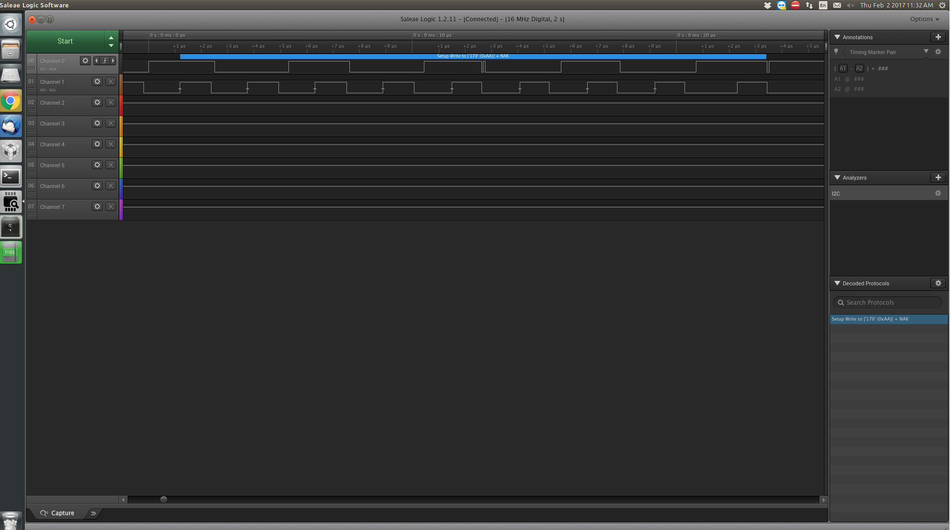
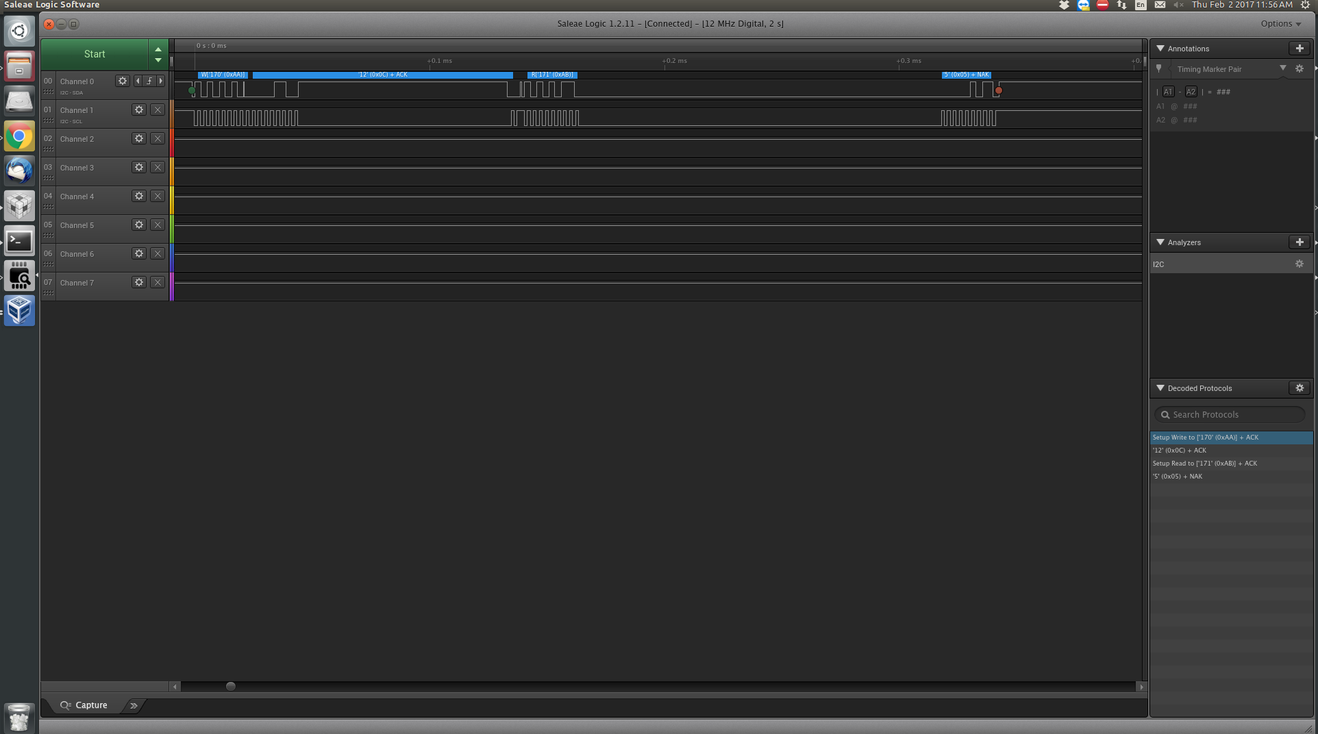
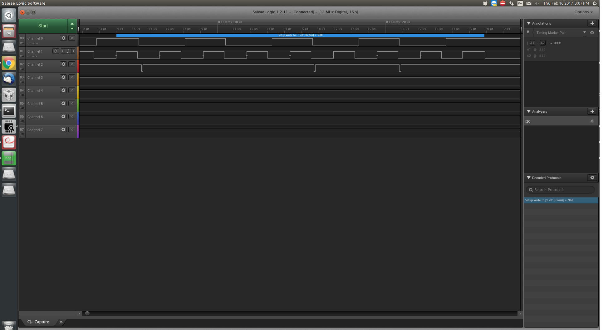
The way I have set it up is MSP430 will be master communicating with slave battery booster pack. I have developed the source code which has two functions to initialize the I2C communication and another one to get battery capacity. The code runs and I can see on Logic it get correct read and write address as well. This is my first project with I2C, so I don't know much stuff about it. On the second byte for command code, I receive NAK. And I don't receive any returned data as well. Any help to figure out what's going wrong will be greatly appreciated. Thanks in advance!
/* * Initialize the I2C communication in between MSP430F5529 LP and Battery * booster pack */ static void ioport_i2c_init(void) { // Assign I2C pins P4.2 (SCL) and P4.1 (SDA) P4SEL |= (BIT2 | BIT1); // P4DIR |= (BIT1); // SMCLK, Software reset enable UCB1CTL1 |= UCSSEL_2 | UCSWRST; // Master mode, I2C mode, Synchronous mode, Address slave with 10-bit UCB1CTL0 = UCMST | UCMODE_3 | UCSYNC;// | UCSLA10; // Baud rate: SMCLK(25MHz)/(400Khz)=62.5=0x3E UCB1BR0 = 0x3E; UCB1BR1 = 0x00; // Slave address UCB1I2CSA = 0x55; // Clear SW reset, to enable operation UCB1CTL1 &= ~UCSWRST; } /* * This function fetches the battery capacity remaining. * * @return * The compensated battery capacity remaining. Units are mAh. */ uint8_t ioport_get_battery_capacity(void) { // Transmitter, Send start condition UCB1CTL1 |= UCTR | UCTXSTT; //Poll for transmit interrupt flag. while(!(UCB1IFG & UCTXIFG)) // If UCTXIFG == 0, then wait { ; // Wait for TXBUF to be empty } if(UCB1IFG & UCTXIFG) { //Send first byte of data UCB1TXBUF = 0x02; printf("Sent 0x0d \n"); } else { printf("Transmit Interrupt pending \n"); } //Poll for transmit interrupt flag. while(!(UCB1IFG & UCTXIFG)) // If UCTXIFG == 0, then wait { ; // Wait for TXBUF to be empty } if(UCB1IFG & UCTXIFG) { //Send second byte of data UCB1TXBUF = 0x03; printf("Sent 0x0c \n"); } else { printf("Transmit Interrupt pending \n"); } /* //Poll for transmit interrupt flag. while(!(UCB1IFG & UCTXIFG)) // If UCTXIFG == 0, then wait { ; // Wait for TXBUF to be empty } if(UCB1IFG & UCTXIFG) { //Send third byte of data UCB1TXBUF = 0x01; printf("Sent 0x01 \n"); } else { printf("Transmit Interrupt pending \n"); } */ // Send stop condition UCB1CTL1 |= UCTXSTP; //////////////////////////////////////////////////////////////////////////// // Reception part when master receives the response // Set master in Receive mode, Send start condition UCB1CTL1 &= ~UCTR; UCB1CTL1 |= UCTXSTT; //Poll for Start bit to complete while(UCB1CTL1 & UCTXSTT) { ; } //Polling RXIFG0 if RXIE is not enabled while(UCB1IFG & UCRXIFG) { //Read a byte from the data received unsigned char PRxData = UCB1RXBUF; printf("Data Received: %c \n",PRxData); } //Send stop condition. UCB1CTL1 |= UCTXSTP; //Wait for Stop to finish while(UCB1CTL1 & UCTXSTP) { ; } return 0; }
Hi Anand,
Just at first glance I see you're trying to send 0x0D and 0x0C but are actually sending 0x02 and 0x03:
if(UCB1IFG & UCTXIFG) { //Send first byte of data UCB1TXBUF = 0x02; printf("Sent 0x0d \n"); } else { printf("Transmit Interrupt pending \n"); } //Poll for transmit interrupt flag. while(!(UCB1IFG & UCTXIFG)) // If UCTXIFG == 0, then wait { ; // Wait for TXBUF to be empty } if(UCB1IFG & UCTXIFG) { //Send second byte of data UCB1TXBUF = 0x03; printf("Sent 0x0c \n"); } else { printf("Transmit Interrupt pending \n"); }
Best regards,
Caleb Overbay
Well just like the remaining capacity of a battery, the booster pack support several other commands too. So I was just trying with those but no luck. Sorry for the confusion, but the command I am interested in RemainingCapacity() with is 0c0C and 0x0D.
Hello Caleb,
Please find attached screenshots from my logic analyzer. I have two battery booster packs and two screenshot shows output received by running code on each of those. To add to my confusion, the output received is different. I think the one which sends back ACK on address 0xAA at least shows some progress whereas other one doesn't acknowledge the address sent. See if you can get anything from these about what's going wrong.
Hi Anand,
Thank you for providing the screenshots. The write with a NAK in response is peculiar to me. Have you ensured you're using the 10K pull-up resistors recommended in the BQ274411-G1 datasheet?
After looking at your code, I see a few things wrong with it. To execute the intended command you can send 0x0C OR 0x0D and you need to follow the following format specified in the BQ274411-G1 datasheet:
What the MSP430 in the above diagram is doing:
This can be accomplished by adopting the following code into your application:
/** * @brief Receive data from bq27441-g1 through i2c bus * @param * @retval 0 : Operation normal * -1 : Could not read data */ int USCI_I2C_READ(char *buffer, int num, int cmd) { char *PRxData; int i=0; // Transmitter, Send start condition with addr + write UCB1CTL1 |= UCTR | UCTXSTT; /* Send command to bq27441 */ if(UCB1IFG & UCTXIFG) { UCB1TXBUF = cmd; } //Timeout for (i=0; i<1000; i++) { if(UCB1IFG & UCTXIFG) break; } /* I2C could not send command * So we could not read data from bq27441 * So we just return */ if (i == 1000) { return -1; } /* Start of RX buffer */ PRxData = buffer; // Receiver, Send restart condition with addr + read UCB1CTL1 &= ~UCTR; UCB1CTL1 |= UCTXSTT; while (num > 0) { for (i=0; i<1000; i++) { if (UCB1IFG & UCRXIFG) { /* Load TX buffer */ *PRxData = UCB1RXBUF; /* Decrement TX byte counter */ num--; PRxData++;
UCB1IFG &= ~UCRXIFG; break; } } if (i == 1000) { return -1; } } //Send stop condition. UCB1CTL1 |= UCTXSTP; /* Clear USCI_B1 TX int flag */ UCB1IFG &= ~UCTXIFG; return 0; }
Can you try this out and let me know the results?
Best regards,
Caleb Overbay
Thanks Caleb for sending the source code example. I have updated my code according to it, and my new code is as follows:
/* * This function fetches the battery capacity remaining. * * @return * The compensated battery capacity remaining. Units are mAh. */ uint8_t ioport_get_battery_capacity(void) { // Transmitter, Send start condition UCB1CTL1 |= UCTR | UCTXSTT; //Poll for transmit interrupt flag. while(!(UCB1IFG & UCTXIFG)) { ; } /* Send command to bq27441 */ if(UCB1IFG & UCTXIFG) { //Send first byte of data UCB1TXBUF = 0x0c; } int i; //Timeout for (i=0; i<1000; i++) { if(UCB1IFG & UCTXIFG) break; } /* I2C could not send command, So we could not read data from bq27441 * So just return */ if (i == 1000) { return -1; } //////////////////////////////////////////////////////////////////////////// // Set master in Receive mode, Send start condition UCB1CTL1 &= ~UCTR; UCB1CTL1 |= UCTXSTT; //Read a byte from the data received char *PRxData; char *buffer; /* Start of RX buffer */ PRxData = buffer; for (i=0; i<1000; i++) { if (UCB1IFG & UCRXIFG) { /* Load TX buffer */ *PRxData = UCB1RXBUF; PRxData++; UCB1IFG &= ~UCRXIFG; break; } } if (i == 1000) { return -1; } for (i=0; i<1000; i++) { if (UCB1IFG & UCRXIFG) { /* Load TX buffer */ *PRxData = UCB1RXBUF; PRxData++; UCB1IFG &= ~UCRXIFG; break; } } if (i == 1000) { return -1; } printf("Data Received: %s \n",buffer); //Send stop condition. UCB1CTL1 |= UCTXSTP; /* Clear USCI_B1 TX int flag */ UCB1IFG &= ~UCTXIFG; return 0; }
Now after the first call to ioport_get_battery_capacity() I receive data 0x03 as first byte. I am not sure whether incoming data is 1 byte or 2. But looks like its doing something. It will be great if you can help me with interpreting the incoming data. Thanks for your help Caleb!
Hi Anand,
The data returned from the BQ27441-G1 is 2-bytes in length so you will need to read from the device twice. So for example, in the code I supplied the while loop that reads from the I2C buffer would need to execute twice (i.e. num = 2 first pass through the loop).
I recommend taking a look at the corresponding MSP430G2 Launchpad code for the BOOTXL-BATTPACK located here:
While it's not for the exact MSP430 or battery fuel gauge you're trying to implement, they are very similar and will help provide insights into interfacing these two devices.
Best regards,
Caleb Overbay
Thanks for sharing that resource. One more problem that I am facing is most of the times, after sending first write instruction, booster pack doesn't acknowledge it. Do we need to wake the booster pack or it is always functioning? (For more information, please find attached screenshot from the logic analyzer.) So I can't communicate with it further. What might be causing this problem?
Hi Anand,
What value pull-up resistors are you using? Also, please check out this new application report on debugging common eUSCI and USCI serial communication issues: Solutions to Common eUSCI and USCI Serial Communication Issues on MSP430 MCUs
Best regards,
Caleb Overbay
**Attention** This is a public forum