This thread has been locked.

If you have a related question, please click the "Ask a related question" button in the top right corner. The newly created question will be automatically linked to this question.

Compiler/MSP430FR5969: SPI data fail

Part Number: MSP430FR5969

Tool/software: TI C/C++ Compiler

Hey everyone. 

I`m trying to put the SPI to work  in MSP430FR5969 with Driverlib but I detect some problems. 

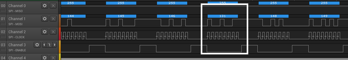
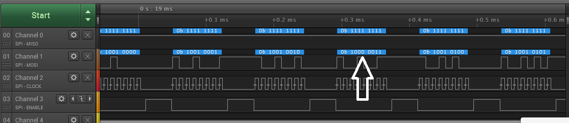
I can transmit the data using polling mode but when I try send the sequence between 0 and 255  the SPI transmit a lot of data wrongly.


My codes are: 

Main Loop:

//I2C_ADDR_DATA_BUFFER_TX(0x53, buffer_test, 6);
for(ia=0; ia<=255; ia++)
{
//I2C_M24LR_WRITE_PAGE(buffer_test, 4*ia);
buffer_test[0]= ia;
SPITXRX (buffer_test[0]);
__delay_cycles(500);
}

SPI INITIALIZATION 

void SPI_INIT(void)
{

/* USER CODE START (section: EUSCI_A1_graceInit_prologue) */
/* User initialization code */
/* USER CODE END (section: EUSCI_A1_graceInit_prologue) */
//Initialize Master

EUSCI_A_SPI_initMasterParam param = {0};
param.selectClockSource = EUSCI_A_SPI_CLOCKSOURCE_SMCLK;
param.clockSourceFrequency = CS_getSMCLK();
param.desiredSpiClock = 100000;
param.msbFirst = EUSCI_A_SPI_MSB_FIRST;
param.clockPhase = EUSCI_A_SPI_PHASE_DATA_CHANGED_ONFIRST_CAPTURED_ON_NEXT;
param.clockPolarity = EUSCI_A_SPI_CLOCKPOLARITY_INACTIVITY_LOW;
param.spiMode = EUSCI_A_SPI_3PIN;
EUSCI_A_SPI_initMaster(EUSCI_A1_BASE, &param);

/* enable eUSCI SPI */
EUSCI_A_SPI_enable(EUSCI_A1_BASE);

/* disable eUSCI SPI transmit interrupt */
EUSCI_A_SPI_disableInterrupt(EUSCI_A1_BASE, EUSCI_A_SPI_TRANSMIT_INTERRUPT);

/* disable eUSCI SPI receive interrupt */
EUSCI_A_SPI_disableInterrupt(EUSCI_A1_BASE, EUSCI_A_SPI_RECEIVE_INTERRUPT);

/* USER CODE START (section: EUSCI_A1_graceInit_epilogue) */
/* User code */
/* USER CODE END (section: EUSCI_A1_graceInit_epilogue) */
__delay_cycles(100);
Init_SPICS();


}

SPI TRASMIT 
unsigned char SPITXRX (unsigned char datatx )
{


CS_LOW();
//
EUSCI_A_SPI_transmitData(EUSCI_A1_BASE,datatx);
while(EUSCI_A_SPI_isBusy(EUSCI_A1_BASE));
CS_HIGH();
return 0;


}


MY HARDWARE AND MY LAUNCHPAD WITH XTAL 14.7656MHZ SHOW THE SAME BIT ERROR. hOW CAN I SOLVE IT?

THANK YOU AND BEST REGARDS. 

  • Hi Carlos,

    I've tested out something similar to this and I'm seeing sporadic results like you are. I then created register level code that does the same thing and the issue was no longer present. I haven't narrowed down the issue yet, but it may have something to do with Driverlib. It would help out tremendously if you could provide your clock initialization code or even your full code for me to test on my setup and debug.

    Best regards,
    Caleb Overbay
  • Hey, Caleb, below my code.  blocks:

    My clock initialization attached . Today during the morning I checked the clock and I saw that my clock is unstable, In theory the P3.4 should put the MCLK out and SMCLK is a division of MCLK. Using External xtal with 14.5456MHz my  clock must but very very stable but im detecting oscilations of 10% in clock frequency in P3.4 output. I`m working to undestand the problem. 

     I`m not sure if driverlib is working well , With I2C i had big problems but now solved. You can check in a figure below. I configure SPI mode 0  Polarity  = 0 and Phase = 0, but my logic analyzer ( Logic Saleae 16 canais ) is   detecting  correct data transmission with  Polarity 1 Phase 0 . 

    I really dont know if driverlib is right or LogiC analyzer. 

    DEF_FRAM.c
    /*
     * DEF_FRAM.c
     *
     *  Created on: 23 de fev de 2017
     *      Author: chnmartins
     */
    #include "DEF_FRAM.h"
    #ifndef MODULE_DEF_FRAM_DEF_FRAM_C_
    #define MODULE_DEF_FRAM_DEF_FRAM_C_
    
    void FRCTL_Init(void)
    {
    	FRAMCtl_configureWaitStateControl(FRAMCTL_ACCESS_TIME_CYCLES_1);
    }


    #endif /* MODULE_DEF_FRAM_DEF_FRAM_C_ */
    
    DEF_FRAM.h
    CLK_SOURCES.c
    /*
     * CLK_SOURCES.c
     *
     *  Created on: 23 de fev de 2017
     *      Author: chnmartins
     */
    #include "CLK_SOURCES.h"
    void Clock_Init(void)
    {
        /*
         * Sets the external clock source for XT1 and XT2. These variables can be used by
         * other API functions.
         *   XT1 Frequency -  32768 Hz
         *   XT2 Frequency -  14745600 Hz
         */
        CS_setExternalClockSource ( 32768, 14745600);
        CS_turnOnLFXTWithTimeout(LFXTDRIVE_3, 100000);  //Start Low Frequency crystal in low frequency mode
        //Start high frequency crystal
        //#define CS_HFXT_DRIVE_8MHZ_16MHZ (HFXTDRIVE_1)
        CS_turnOnHFXTWithTimeout(HFXTDRIVE_1, 100000);
        //Setting MCLK source from CS_HFXTCLK_SELECT with the divider of CS_CLOCK_DIVIDER_1.
        CS_initClockSignal (CS_MCLK, CS_HFXTCLK_SELECT, CS_CLOCK_DIVIDER_1);
        //etting SMCLK source from CS_HFXTCLK_SELECT with the divider of CS_CLOCK_DIVIDER_4.
    
        CS_initClockSignal ( CS_SMCLK, CS_HFXTCLK_SELECT, CS_CLOCK_DIVIDER_4);
    
        /*
         * Setting ACLK source from CS_LFXTCLK_SELECT with the divider of CS_CLOCK_DIVIDER_32.
         */
        CS_initClockSignal  (CS_ACLK, CS_LFXTCLK_SELECT, CS_CLOCK_DIVIDER_32);
    
        /*
         * Set DCO frequency to 16000000 Hz
         */
        CS_setDCOFreq (CS_DCORSEL_0, CS_DCOFSEL_6);
    
        /*
         * Clears all oscillator fault flags including global oscillator fault flag
         * before switching clock sources
         */
        CS_clearAllOscFlagsWithTimeout(100000);
    
        /*
         * MCLK clock request enable. Setting this enables conditional module requests for MCLK
         */
        CS_disableClockRequest ( CS_MCLK);
    
        /*
         * SMCLK clock request enable. Setting this enables conditional module requests for SMCLK
         */
        CS_disableClockRequest (CS_SMCLK);
    
        /*
         * ACLK clock request enable. Setting this enables conditional module requests for ACLK
         */
        CS_disableClockRequest (CS_ACLK);
    }
    
    void Enable_SMCLK_Output_3P4(void)
    {
        /* Port 3 Port Select Register 1 */
        P3SEL1 = BIT4;
        /* Port 3 Direction Register */
        P3DIR = BIT4;
    }
    
    
    void Init_HF_XTAL_PIN(void)
    {
         //  XT1 Frequency -  32768 Hz
         //  XT2 Frequency -  14745600 Hz
         // Port 4 Interrupt Flag Register
         	P4IFG = 0;
         // Port J Output Register
         	PJOUT = 0;
         // Init Low frequency xtal pin
         	PJSEL0 = BIT4 | BIT5;
         // Init High Frequency Xtal Pin
            PJSEL0 = BIT6 | BIT7;
         // Port J Direction Register */
            PJDIR = 0;
    }
    
    void Start_up_clock_system(void)
    {
    	FRCTL_Init();
    	Init_HF_XTAL_PIN();
    	Enable_SMCLK_Output_3P4();
        Clock_Init();
    }


    CLK_SOURCES.h

  • Hi Carlos,

    In the image you've posted, your code says data is changed on the first edge and captured on the second. In other words, this means the code is valid on the trailing edge which is why the logic analyzer correctly interprets it with the settings shown.

    Instead of using the external xtal, can you run the SMCLK off the DCO as an experiment to see if it is the clock stability that is causing an issue?

    Best regards,
    Caleb Overbay

**Attention** This is a public forum