This thread has been locked.

If you have a related question, please click the "Ask a related question" button in the top right corner. The newly created question will be automatically linked to this question.

MSP430G2955: MSP430 Master receiver I2C not working!!!

Part Number: MSP430G2955

Hello everyone,

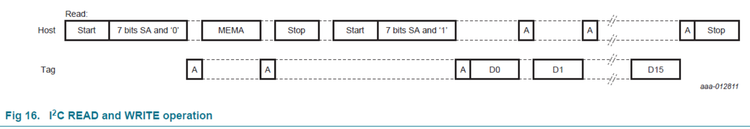
i am currently  working in interfacing the NFC NTAG I2C (NT3H1101/NT3H1201 )with the MSP430, so i want to receive 16 bytes of data, in my code when i run it step by step my code stop at the     while(UCB0CTL1 & UCTXSTT);             // Ensure START condition got sent

(UCB0CTL1 & UCTXSTT);             // Ensure START condition got sent
i have looked at the example given by TI msp430g2x55_uscib0_i2c_04.c and still have failed to understand why they statred by this instruction as the msp430 is the responsible for sending a stop condiction
 while (UCB0CTL1 & UCTXSTP);             // Ensure stop condition got sent

here below you can see my code

#include <msp430g2955.h>


/*
 * main.c
 */

//***declaration of global variable***************************
unsigned char *ptrRx;
unsigned char RXData[10];


int main(void) {
    WDTCTL =  WDTPW + WDTHOLD;//Stop the WDT to prevent reset
    BCSCTL1 = CALBC1_16MHZ;                    // Set DCO to 16MHz
    DCOCTL =  CALDCO_16MHZ;

    i2c_init(
            );

    while(1){
        i2c_read_interrupt_init(RXData,1);

    }

	
	return 0;
}
//initialization
void i2c_init(void){
    // configure P3.1(SDA) an P3.2(SCL) for I2C
    P3SEL =BIT1|BIT2;
    P3SEL2 &=~(BIT1|BIT2);

    //Ensure that the USCI_B0 is reset before the configuration
    UCB0CTL1 |=UCSWRST;
    //slve adrres with 7 bit
    UCB0CTL1 &=~UCSLA10;
    //set the MSP430 to master mode
    UCB0CTL0 |=UCMST|UCMODE_3|UCSYNC;
    //take USCi clock source from SMCLK
    UCB0CTL1|=UCSSEL_3;
    //configure the baud rate registers for 100Khz when sourcing from SMCLK,SMCLK=16Mhz
    UCB0BR0 =80;//lower byte of UCBRx
    UCB0BR1 =0;
    //writing the slave address
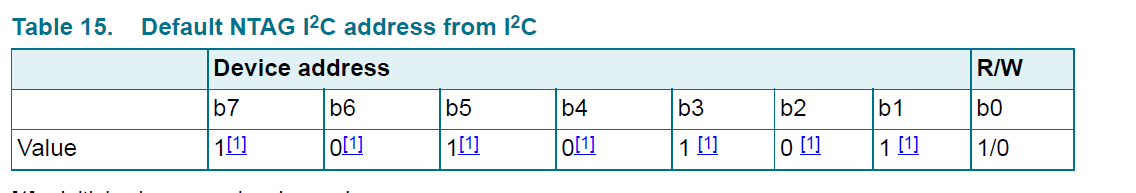
    UCB0I2CSA =0xAA;
    // Clear SW reset, take the USCI module out of reset
    UCB0CTL1 &=~UCSWRST;
    // enable Rx interrupt
    IE2 |=UCB0RXIE;

}

//receive function

void i2c_read_interrupt_init(unsigned char *rxbuf,unsigned char length){
    unsigned char i;
    //receiver mode
    UCB0CTL1 &=~UCTR;
    UCB0CTL1 |= UCTXSTT;                    // I2C start condition
    while (UCB0CTL1 & UCTXSTT);             // Ensure START condition got sent
    __bis_SR_register(LPM0 | GIE);        // Enter LPM0 w/ interrupt

    for(i=0;i<length;i++){
    while(!(IFG2&UCB0RXIFG));     //wait tiill we receive the data
    *rxbuf=RXByte;
    rxbuf++;
    }
    if(length==1){
        //stop reception
        UCB0CTL1 |=UCTXSTP;
    }
}
// interrupt
#pragma vector = USCIAB0RX_VECTOR
__interrupt void USCIAB0RX_ISR(void)
{
    //clear interrrupt flag
  RXByte = UCB0RXBUF;                       // Get RX data
  __bic_SR_register_on_exit(LPM0);        // Exit LPM0
}

  • Hi tarik,

    The example code is demo how to setup USCIB0 I2C master mode and communcation between two MSP430G2955 device, If you want to read other i2c device like NT3H1101/NT3H1201, the code should refer to the I2C protocol on datasheet as below:

    regards

    KC

  • Hello KC,
    i have looked at the datasheet ass you said but i have some issue to understand the R/W bit, so in the MSP430 Master Receiver i have to clear the UCTR for reading, Set the UCTR for Writing and in the NTAG NFC it says the opposite R/W =0(write), R/W=1(Read).so i dont really know how to use this bit according to the MSP430 and NTAG NFC as they seem to be opposite.thanks
  • Hi Tarik,

    when set UCTR, R/W = 0 (write), clear the UCTR, R/W =1(Read).

    Regards
    KC
  • void i2c_read_interrupt_mem(unsigned char *rxbuf,unsigned char length,unsigned char MEMA){
        unsigned char i;
        //transmitter mode for memory address
        UCB0CTL1 |=UCTR; //transmitter
        UCB0CTL1 |= UCTXSTT;                    // I2C start condition
        while (UCB0CTL1 & UCTXSTT);             // Ensure START condition got sent
        //send memory address
        UCB0TXBUF=MEMA;
        while ((UCB0CTL1 & UCTXSTT) && (!(IFG2 & UCB0TXIFG)));            // Ensure START condition got sent and memory address is being read
    
        //stop condition
        UCB0CTL1 |=UCTXSTP;
        //receiver mode
        UCB0CTL1 &=~UCTR;
        UCB0CTL1 |= UCTXSTT;                    // I2C start condition
    
    //receiver mode
        __bis_SR_register(LPM0 | GIE);        // Enter LPM0 w/ interrupt
    
        for(i=0;i<length;i++){
        while(!(IFG2 & UCB0RXIFG));     //wait till we receive the data
        *rxbuf=RXByte;
        rxbuf++;
        }
        if(i==1){
            //stop reception
            UCB0CTL1 |=UCTXSTP;
        }
    }

    Hi KC,

    thank you for clearing my doubt.Now, i get the point. however i have modified my code according to the NTAG NFC and still my code stops at this line of code:

       while (UCB0CTL1 & UCTXSTT);             // Ensure START condition got sent

    and while checking on the Logic Analyser,the SCL is All the time high and i see many random data on the SDA which does not make any sense

  • Hi Tarik,

    After USCI generates the START condition and transmits the salve address, USCI will clear UCTXSTT bit as soon as the slave acknowledges the address. Your code stops there means USCI does not get acknowledges from slave device.

    It's strange that SCL is all the time high, need check HW if it possbile SCL be hold high by some reason. At least slave address 0xAA should be transmitted correctly.

    regards
    KC
  •  Hello KC,

    i have run my code with the address of 0x55 because i thought i have to shift it by my self and i made a mistake by choosing the clock of 200kh i get an ack with adress 0xAA.nevertheless, i have seen the SCL frequency at 200khz without any problem. but since that i keep seeing the SCL high whenever i burn the code on the msp430, which makes it weird. i run as well the last change i made to 100khz clock but still the same problem

  • Hi Tarik,

    Do you have the backup code which can work under 200K? Then you can compare the different of code or register setting when doing transmittion. Hope this help.

    regards
    KC
  •  Hi KC,
    the backup code is exactly the same. i have just changed the value from 80 to 160 (16Mhz to get 100khz) of this code line:UCB0BR0 =80;//lower byte of UCBRx
    so, it worked once for both of them afterthat nothing shows proper data an the SCL is all time high.

  • Hi tarik,

    Sorry for late response, have you solved the issue now?

    regards
    KC
  • Hello Kc,
    unfortunatly, i still struggling with it
  • Hi tarik,

    Could you send me the SCH and code file?

    regards
    KC
  • Hello KC,
    yhank you for your help, I will send it to you the screenshot of the logic analyser

**Attention** This is a public forum