This thread has been locked.

If you have a related question, please click the "Ask a related question" button in the top right corner. The newly created question will be automatically linked to this question.

MSP430F5329: Is there example code for I2C that will run on a MSP430F5329?

Part Number: MSP430F5329

I need simple code to read and write to I2C devices. The MSP430 is one master and the others are silicon devices. 

I find it amazing that you have so many variants of your peripherals that I can not find code that just works without a lot of messaging. 

Google searching did not help. 

My first thing I found was some code from Jan Richter http://hackaday.com/2014/02/02/a-better-usi-i2c-library-for-the-msp430/
I
t was written for a different version of the MSP430 but I figured it should be nearly the same right? Wrong. It assumed a USI I2C where the  MSP430F5329 used a USCI I2C and they are not alike as I wasted a few days trying to get it to work. It was too different. 

Found the MSP430 I2C Wiki http://processors.wiki.ti.com/index.php/MSP430_I2C
I
t said "Each MSP430 product page has Code Examples .zip file under Software & Tools --> Software"

So I looked there and did find a file that said MSP430F532x Code Examples (Rev. F)  (ZIP217KB )   164views,05 Jun 2017  
I thought I was golden until I looked at the code examples for I2C. 

Here is the example I2C interrupt routine.

// USCI_B0 Data ISR
#if defined(__TI_COMPILER_VERSION__) || defined(__IAR_SYSTEMS_ICC__)
#pragma vector = USCI_B0_VECTOR
__interrupt void USCI_B0_ISR(void)
#elif defined(__GNUC__)
void __attribute__ ((interrupt(USCI_B0_VECTOR))) USCI_B0_ISR (void)
#else
#error Compiler not supported!
#endif
{
  switch(__even_in_range(UCB0IV,12))
  {
  case  0: break;                           // Vector  0: No interrupts
  case  2: break;                           // Vector  2: ALIFG
  case  4: break;                           // Vector  4: NACKIFG
  case  6: break;                           // Vector  6: STTIFG
  case  8: break;                           // Vector  8: STPIFG
  case 10:                                  // Vector 10: RXIFG
    RXData = UCB0RXBUF;                     // Get RX data
    __bic_SR_register_on_exit(LPM0_bits);   // Exit active CPU
    break;
  case 12: break;                           // Vector 12: TXIFG
  default: break; 
  }
}

Not very helpful, and not what I would call a real example. 


I thought I had it with the SLAA382A --  Using the USCI I2C master. 
I downloaded the example from SLAA382A which says it is for a USCI I2C Master. But he is using a "MSP430x261x" which uses different pins, different USCI (UCB0 not UCB1), and has separate interrupts for I2C read and write.  So it is going to take some work to get to a point to find out where the problems are for my specific device. I already wasted days going down the wrong path. 


Why is there not example code for each of your processors?  Why so many different I2C peripherals? Get one that works and keep using it. It is not like it is a new interface. 

What am I supposed to do? Where do I start? 

We are switching from a ST ARM processor to the MSP430 and because we had problems with the I2C on the ST we had to bit-bang the I2C on the ST part. My colleague rewrote the bit-bang code from the ST part to the MSP430 in a day (basically he changed pin names and the timing delay loop), and I can not get it working using the MSP430 I2C peripherals in a week.


 

  • So I unzipped SLAA382A. Changed P3SEL to P4SEL and changed all of the UCB0 to UCB1 and compiled to see what I have. 17 compile errors because Special Function registers have different names.

    I got errors on these names. UCB1I2CIE, IE2, USCIAB0RX_VECTOR, USCIAB0TX_VECTOR, IFG2
  • Browsing the code found this:

    //------------------------------------------------------------------------------
    // unsigned char TI_USCI_I2C_notready()
    //
    // This function is used to check if there is commuincation in progress.
    //
    // OUT:  unsigned char  =>  0: I2C bus is idle,
    //                          1: communication is in progress
    //------------------------------------------------------------------------------
    unsigned char TI_USCI_I2C_notready(){
      return (UCB1STAT & UCBBUSY);
    }

    UCBBUSY is bit 4 in UCB1STAT register. 

    That means this returns 0 or 16, not 0 or 1.

  • There are eight example programs for this chip. Each one illustrates something different.

    These example programs show how to access the hardware, but are not intended to be independent tutorials. They assume that you are reading chapter 38 of the User's Guide.
  • Of course you are referring to:

    MSP430F532x_uscib0_i2c_04.c USCI_B0 I2C Master RX single bytes from MSP430 Master
    MSP430F532x_uscib0_i2c_05.c USCI_B0 I2C Slave TX single bytes to MSP430 Slave
    MSP430F532x_uscib0_i2c_06.c USCI_B0 I2C Master TX single bytes to MSP430 Slave
    MSP430F532x_uscib0_i2c_07.c USCI_B0 I2C Slave RX single bytes from MSP430 Master
    MSP430F532x_uscib0_i2c_08.c USCI_B0 I2C Master TX multiple bytes to MSP430 Slave
    MSP430F532x_uscib0_i2c_09.c USCI_B0 I2C Slave RX multiple bytes from MSP430 Master
    MSP430F532x_uscib0_i2c_10.c USCI_B0 I2C Master RX multiple bytes from MSP430 Slave
    MSP430F532x_uscib0_i2c_11.c USCI_B0 I2C Slave TX multiple bytes to MSP430 Master

    Most people are interested in a processor being a master, and talking to some slave IC device. It could be memory, it could be a peripheral, os some other special chip. 

    The pattern is pretty straight forward. You have to write a Peripheral address. Then probably an address inside the device. Then if you are writing, continue writing. If you are reading do a restart and do a read on a peripheral address then multiple reads. 

    No examples of that. It is the most common and basic interaction on the I2C bus. 

    Having multiple masters, or using I2C to talk between processors is more rare and is more advanced. It is good that you can do it, but you have it mixed in with the documentation on the I2C Master Transmitter Mode, which makes the documentation harder to read. 

    But the part that is really annoying, and the reason you probably do not have good examples, is that the different MSP430 processors have different I2C peripherals and different register names. So it is almost like starting over when you change from one MSP430 to another MSP430. And that is why I will try to switch this project away from a MSP430 to another architecture where that is not the issue. 

    Why do you use ICB1IE in one MSP430 and ICB1I2CIE and IE2  in another MSP430? 


    But in the meantime I still have to work with this one for now. 

    So looking at MSP430F532x_uscib0_i2c_08.c USCI_B0 I2C Master TX multiple bytes to MSP430 Slave it shows how to send multiple bytes. 


    So we will do this the hard way. 

    I have a MSP430F5329 and I am talking to a bq7692006PWR which has an address of 0x18 and no CRC. 


    I initialize it with the following code:

    void i2c_init(void)
    {
      // Setup pins
      P4SEL |= 0x06;            // Setup as P4.1 (SDA), P4.2(SCL) as Special Function pins
    
      __disable_interrupt();
      i2c_interrupt_count = 0;
      UCB1CTL1 = 0x81;          // Clock is SMCLK, Do not interrupt on erroneous character
                                // do not interrupt on break character
                                // Not dormant, next frame is data, next frame is not a break,
                                // I2C is held in reset.
    
      UCB1BR0 = 148;            // Set bit rate to 14745600 / 148 = 99632.43 bps
      UCB1BR1 = 0;
    
      UCB1CTL0 = 0x0F;          // 7 Bit addressing, Single Master
                                // Master mode select, I2C mode, Synchronous Mode
    
      i2c_state = I2C_IDLE;     // Make sure state machine is in idle
      UCB1CTL1 &= ~(UCSWRST);   // Clear I2C Reset now I2C is setup and ready.
    
    
      UCB1IE = 0x03;            // Enable Transmit and Receive Interrupt
      UCB1IFG = 0;              // Clear all interrupt flags.
    
      //__enable_interrupt();   // normally set interrupt here. do it without interrupts until it works. 
    
    #ifdef testbq796
      test_i2c();
    #endif
    }

    test sets up a sequence of data. 

    const uint16_t i2c_testdata_sequence1[] = { bq769x_Address_WR_t, 0, I2C_RESTART, bq769x_Address_RD_t, I2C_READ, I2C_READ, I2C_READ };

    So we want to write bq769 address (0x18 + 0 for write), then send the bq769 an address of 0 of where we want to read. Then perform a restart with a read of the part at address (0x18 + 1 for read), then read three times

    to get data from address 0, 1, and 2.

    So with no interrupts going I execute the following code:

    void start_communications(void)
    {
        uint16_t i;
        UCB1CTL1 |= UCTR | UCTXSTT;     // Transmitter and Transmit START
    
        UCB1I2CSA = ((char)(*i2c_sequence)) >> 1; // Load I2C Address without r/w bit byte
    
        i2c_sequence++;
        i2c_sequence_length--;
    
        i2c_prepare_data_xmit_recv();
        i2c_state = I2C_PREPARE_ACKNACK; // next state: prepare to receive data ACK/NACK
    
        while(UCB1IFG == 0); // wait for any interrupt flag
    
        for (i=0;i<10; i++); // debug break here
    
    }

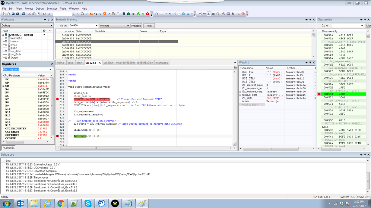
    So looking at the interrupt flags, UCB1IFG, I get 0x22.  This means I got a UCNAKIFG and got a UCTXIFG.  I expected the TX interrupt, did not expect the NAK interrupt. 

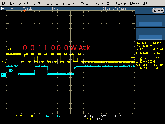
    Looking at the Oscilloscope with Yellow being SCL and Blue being SDA

    It looks correct to me if the address is 0x18 See the attached file NAK. 

    If the Oscilloscope says there was a Ack, why is UCNAKIFG a 1?


    You can see the watch 1 window says UCB1IFG = 0x22. 

    So what am I doing wrong? 

    According to the Documentation a ACK is a 1

    In SLAU412E Page 13 it says 

    1.3.4.2.1 I 2 C Master Transmitter Mode

    After initialization, master transmitter mode is initiated by writing the desired slave address to the
    UCBxI2CSA register, selecting the size of the slave address with the UCSLA10 bit, setting UCTR for
    transmitter mode, and setting UCTXSTT to generate a START condition.

    The USCI module checks if the bus is available, generates the START condition, and transmits the slave
    address. The UCTXIFG bit is set when the START condition is generated and the first data to be
    transmitted can be written into UCBxTXBUF. As soon as the slave acknowledges the address, the
    UCTXSTT bit is cleared.

    It looks like UCTXSST is cleared so the slave acknowledged the address. Which we confirm from scope image.

    RycherI2CRevC.zip

    I included the full source file. 

  • These example programs use a MSP as the slave because it does not matter what kind of device the slave is; I²C just transfers bytes. There are no multiple masters.
    One problem that these examples have is that they do not show how to handle a repeated start.

    In the waveform shown, the last bit is high; this is not an ACK but a NAK. (What slave are you using?)

    USI and USCI are different hardware modules. The code from Jan Richter is for USI and is not helpful for the F5329.

    The SLAA382 code is for 2xx devices. I don't know why TI moved the interrupt flags around; I'd guess that 5xx devices can have more USCI modules so that the bits would not fit into a single register. Anyway, this code does not support repeated start either.

    The following (untested) code does a register read, without interrupts and without error checking:

    void init_i2c(void)
    {
        UCB1CTL1 = UCSSEL__SMCLK + UCSWRST;
        UCB1CTL0 = UCMST + UCMODE_3 + UCSYNC;
        UCB1BRW = 148;
        UCB1CTL1 &= ~UCSWRST;
    }
    
    void write1_read3(void)
    {
        UCB1I2CSA = 0x18;
    
        UCB1CTL1 |= UCTR + UCTXSTT;
    
        while (!(UCB1IFG & UCTXIFG)) ;
        UCB1TXBUF = 0x00;
    
        UCB1CTL1 &= ~UCTR;
        UCB1CTL1 |= UCTXSTT;
    
        while (!(UCB1IFG & UCRXIFG)) ;
        byte1 = UCB1RXBUF;
    
        while (!(UCB1IFG & UCRXIFG)) ;
        byte2 = UCB1RXBUF;
    
        UCB1CTL1 |= UCTXSTP;
        while (!(UCB1IFG & UCRXIFG)) ;
        byte3 = UCB1RXBUF;
    }
  • I did discover Jan Richters code was for USI and not USCI, but I liked how he made a state machine in the interrupt so I could specify a sequence and the communications would happen in the background and I would be able to deal with the received data after it was done.

    But then I discovered I had more basic problems just making it talk.

    On the I2C bus we have 3 slave devices: BQ34Z100PWR, BQ7694006DBT, and MCP47FEB22A0-E/ST

    I was told they had I2C problems with the  BQ34Z100PWR and a ST32 processor. To fix it, they went to not using the I2C HW but bit-banged it.

    They were able to convert the bit-bang code to the MSP430 and got it to work.

    My job is to get the I2C code to work, so the processor can be off longer to save battery.

    I am starting with the BQ7694006DBT because they did not have any problems with that.  Then I will tackle the BQ34Z100PWR to discover what problems they had with that chip.  And if it is a slave problem or a master problem.  I do not know I am getting information second or third hand. The ST32 code was written in Asia. The bit-bang fix for the ST32, and conversion to the MSP430 was written in Austin, and I am in Plano.

    I ran your code example.  At the point where we sent the slave address you got the same thing I got. During the while (!(UCB1IFG & UCTXIFG)) ; After sending the slave address, UCB1IFG = 0x22,  just like the issue above. The UCNAKIFG and UCTXIFG bits are set.  If I was using this in an interrupt (which is where I want to go) the UCB1IV register would have UCNAKIFG interrupt because it has a higher priority. But I do not understand why the processor thinks I am getting a NAK, because a NAK is a 0 and a ACK is a 1 and I see a 1 on the scope.  So that is problem #1. Why a NAK when it looks like a ACK?

    Problem number 2:

    it gets stuck in the next while.  your code says:

        UCB1TXBUF = 0x00;
    
        UCB1CTL1 &= ~UCTR;
        UCB1CTL1 |= UCTXSTT;
    
        while (!(UCB1IFG & UCRXIFG)) ;

    but at the 

     while (!(UCB1IFG & UCRXIFG)) ;

    UCB1IFG = 0x20 which is still the NACK.  So do I need to clear the NAK before I send the 0x00? And should the while be after the 

    UCB1TXBUF = 0x00;

    because it is being sent. (I did not see it come out on the oscilloscope.)

    I am going to play with a little and see what happens.


    |


  • You get UCNAKIFG because there is a NAK on the bus. NAK is 1 (high level).
    (And after a NAK, you must not continute with the transfer.)

  • I changed your code a little. It now looks like this.

    void write1_read32(void)
    {
        UCB1I2CSA = 0x18;
    
        UCB1CTL1 |= UCTR + UCTXSTT;
    
        while (!(UCB1IFG & UCTXIFG)) ;
    
        UCB1IFG = 0;
        UCB1TXBUF = 0x00;
        while (!(UCB1IFG & UCTXIFG)) ;
    
    
        UCB1CTL1 &= ~UCTR;
        UCB1CTL1 |= UCTXSTT;
    
        while (!(UCB1IFG & UCRXIFG)) ;
        byte1 = UCB1RXBUF;
    
        while (!(UCB1IFG & UCRXIFG)) ;
        byte2 = UCB1RXBUF;
    
        UCB1CTL1 |= UCTXSTP;
        while (!(UCB1IFG & UCRXIFG)) ;
        byte3 = UCB1RXBUF;
    }
    

    The first "while" is passed as soon as I can put data into the UCB1TXBUF. 

    The documentation says:

    The USCI module checks if the bus is available, generates the START condition, and transmits the slave
    address. The UCTXIFG bit is set when the START condition is generated and the first data to be
    transmitted can be written into UCBxTXBUF. As soon as the slave acknowledges the address, the
    UCTXSTT bit is cleared.

    We still have the problem with the UCNAKIFG but I ignore it by setting the UCB1IFG register to 0

    Then I write the 0x00 to the UCB1TXBUF buffer and wait for it to be sent.

    The data written into UCBxTXBUF is transmitted if arbitration is not lost during transmission of the slave
    address. UCTXIFG is set again as soon as the data is transferred from the buffer into the shift register. If
    there is no data loaded to UCBxTXBUF before the acknowledge cycle, the bus is held during the
    acknowledge cycle with SCL low until data is written into UCBxTXBUF. Data is transmitted or the bus is
    held, as long as the UCTXSTP bit or UCTXSTT bit is not set.

    The data was not written. (According to the oscilloscope. It looks the same as above, the slave address is written only.) I have only one master so I do not know how I could have lost arbitration. But UCTXIFG is not set.
    UCB1IFG = 0x20 because the NAK happened after I cleared UCB1IFG.

    So I am still stuck at the same place. 
     

  • The slave did not ACK. You cannot transmit anything because the transaction did not get started; clearing NAKIFG does not change that.
  • NAK is 1? That is a problem.

    I can not find in the documentation where it says what a ACK or NAK is. Everytime it just says ACK bit. Nowhere does it say ACK is high or low.

    That means it does not see my device.
  • https://en.wikipedia.org/wiki/I²C#Physical_layer

    The waveforms look OK. Might be a wrong connection to the slave, or wrong voltage levels.

  • I made a little progress, I switched addresses to another device on the I2C bus and started getting valid responses.

    So something happened to the BQ7694006DBT. They said this board worked when they gave it to me. :(

    I tried to write a loop that would scan all 128 addresses to see which ones would ACK (to see of it is at another address), but it looks like it sends out the data on one address and I cannot get it to do another unless I cycle power. I tried adding a stop, and reinitializing the registers. Is there a secret I need to know?


    Still working on it, but now that something works, progress should improve quickly.

**Attention** This is a public forum